Backlight system, liquid crystal display including the same, and method of adjusting backlight

a liquid crystal display and backlight technology, applied in the direction of illuminated signs, display means, instruments, etc., can solve the problems of deteriorating display quality, display darkness, inverter generation noise, etc., and achieve low deviation in color and favorable white balance

Inactive Publication Date: 2007-10-18
NEC LCD TECH CORP
View PDF1 Cites 40 Cited by
  • Summary
  • Abstract
  • Description
  • Claims
  • Application Information

AI Technical Summary

Benefits of technology

[0011]Accordingly, an exemplary feature of the present invention is to provide a backlight system, an LCD device including the backlight system, and a method of adjusting

Problems solved by technology

However, peripheral circuits such as an inverter are required for turning on the fluorescent lamp, and such an inverter generates noise.
This brings about a problem of deterioration in the display quality.
This leads to a problem that the display becomes dark, as compared with the case where all the LEDs are constantly on.
However, the light emitting characteristics of LEDs and the amount of light emitted from the LEDs are not constant, and change with time.
As a result, it is difficult to obtain visually desired luminance, luminance uniformity and white balance

Method used


Image

  • Backlight system, liquid crystal display including the same, and method of adjusting backlight
  • Backlight system, liquid crystal display including the same, and method of adjusting backlight
  • Backlight system, liquid crystal display including the same, and method of adjusting backlight

Examples


first exemplary embodiment

[0045]A backlight system, an LCD device including the backlight system, and a method of adjusting a backlight according to a first exemplary embodiment of the present invention are described with reference to FIGS. 1 to 3.

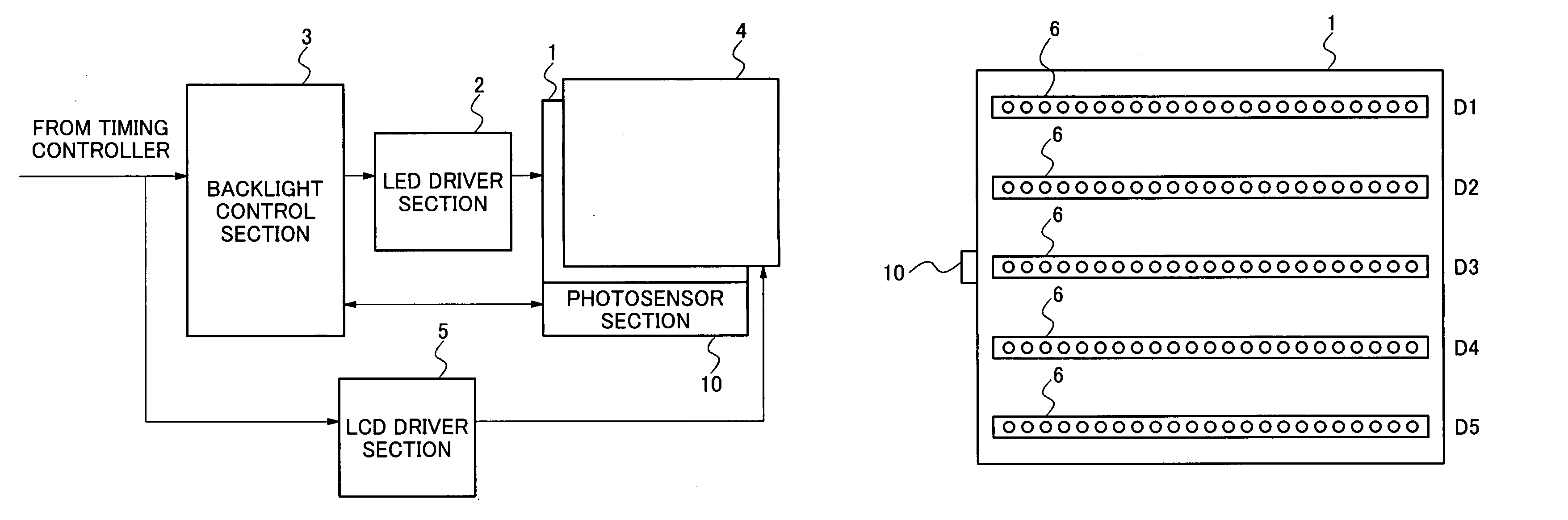
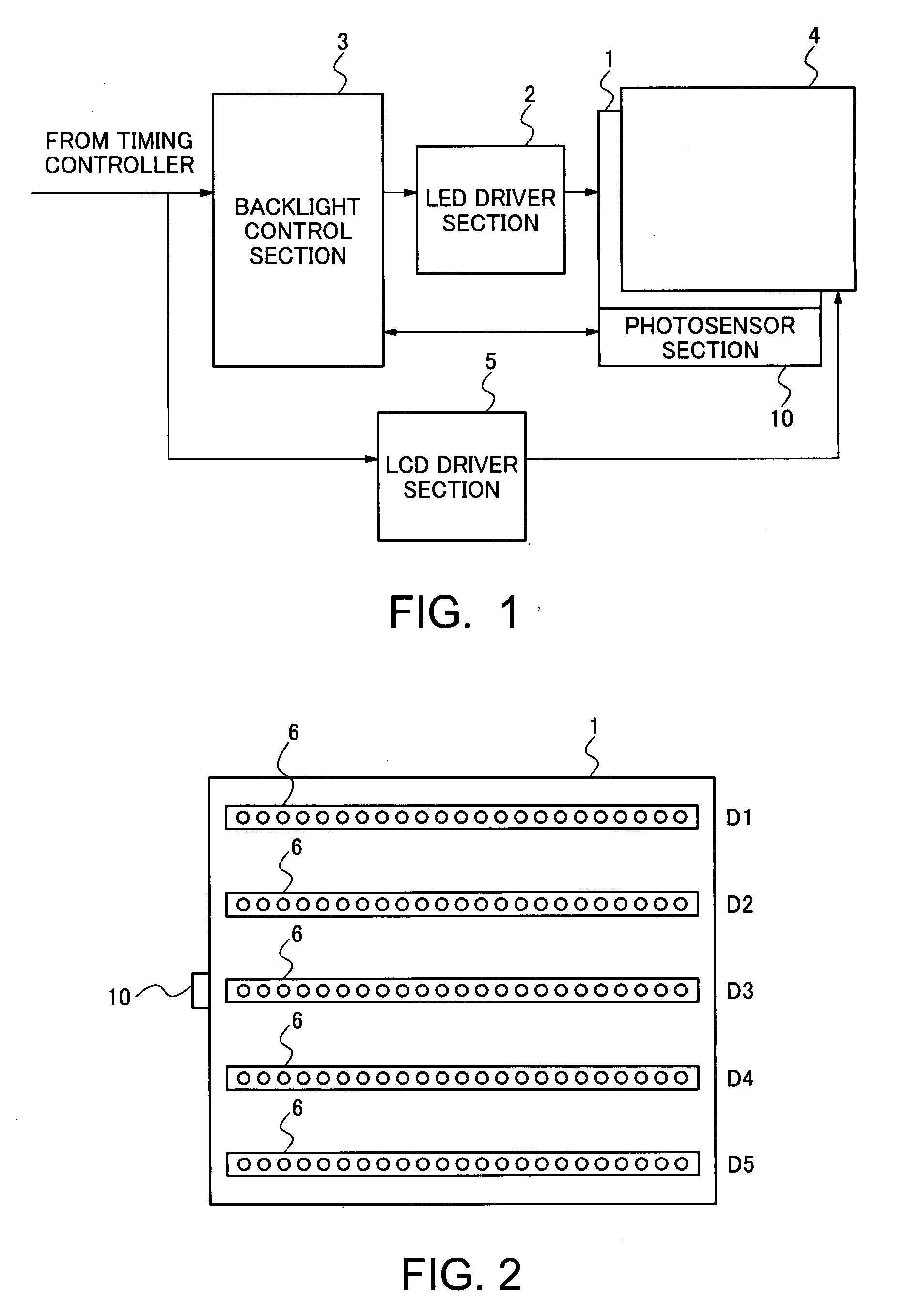
[0046]As shown in FIG. 1, a backlight system according to this embodiment includes an LED section 1, an LED driver section 2, a photosensor section 10, a backlight control section 3. The LED section 1 includes plural LEDs. The LED driver section 2 drives the LED section 1. The photosensor section 10 detects light from the LED section 1, and the backlight control section 3 controls the LED driver section 2 and the photosensor section 10. Moreover, an LCD device including the backlight system according to this embodiment includes the LED section 1, the LED driver section 2, the photosensor 10, the backlight control section 3, an LCD panel 4, an LCD driver section 5 and the like. In the LCD panel 4, liquid crystal layer is held between a pair of substrates. The LED dr...

second exemplary embodiment

[0055]Next, a backlight system, an LCD device including the backlight system, and a method of adjusting a backlight in a second exemplary embodiment of the present invention are described with reference to FIGS. 4 to 6. In the present embodiment, the entire configuration of the backlight system and the details of the photosensor section 10 are the same as those in the first exemplary embodiment shown in FIGS. 1 and 3. Accordingly, the description thereof will be omitted.

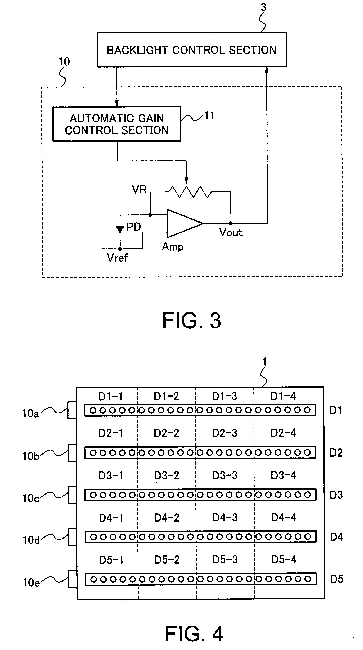
[0056]In the above-described first exemplary embodiment, one photosensor section 10 is used for plural LED units. On the other hand, in the second exemplary embodiment, as shown in FIG. 4, photosensor sections 10a to 10e are disposed respectively in vicinities of ends of LED units D1 to D5, in a longitudinal direction of each LED unit. In each of the LED units D1 to D5, LEDs of plural luminescent colors such as RGB are linearly arranged. Thereby, the photosensor sections 10a to 10e are configured to detect light emit...


PUM


Abstract

A photosensor section is disposed in a vicinity of the center of a shorter side of an LED panel including plural arrays of LED units in each of which plural LEDs are arranged. A gain of the photosensor section is adjusted on the basis of gain correction information set in advance according to the position of each LED unit. Thereby, the calibration of the photosensor section is performed. While the photosensor section, which has been adjusted in this manner, sequentially detects the amounts of light from the LED units, a backlight unit emits backlight toward a liquid crystal display panel.

Description

BACKGROUND OF THE INVENTION[0001]1. Field of the Invention[0002]The present invention relates to a backlight system, a liquid crystal display device including the backlight system, and a method of adjusting a backlight.[0003]2. Description of the Related Art[0004]A liquid crystal display (LCD) device has features of a small size, a thin shape and low power consumption. For this reason, an LCD device has been widely used for office automation (OA) equipment, audio and visual (AV) equipment, a portable terminal device or the like. The LCD device is provided with a backlight source at the back side of an LCD panel. In the LCD device, an image is displayed by controlling the transmission of light emitted from the backlight source by using liquid crystal layer. As the backlight source, a fluorescent lamp is generally used. However, peripheral circuits such as an inverter are required for turning on the fluorescent lamp, and such an inverter generates noise. For these reasons, a light emi...

Claims


Application Information

Patent Timeline
IPC IPC(8): F21V23/04
CPCG09G3/342G09G3/3426G09G2360/145G09G2320/064G09G2320/0666G09G2320/0626
Inventor NISHIGAKI, EITARO
Owner NEC LCD TECH CORP
Why Eureka
Try Eureka