Chattering vibration inhibiting mechanism of machine tool

Active Publication Date: 2007-10-18
DMG MORI SEIKI CO LTD
View PDF10 Cites 16 Cited by
  • Summary
  • Abstract
  • Description
  • Claims
  • Application Information

AI Technical Summary

Benefits of technology

[0016] In this embodiment, the box-shaped package body is disposed on such an end surface of the spindle head that is opposite to the end surface equipped with the tool, namely the chattering vibration i

Problems solved by technology

In a machine tool, accuracy in machining of a work possibly degrades due to chattering vibration generated in the machining of the work.
Meanwhile, a structure disposing a container accommodating many solid fine particles

Method used


Image

  • Chattering vibration inhibiting mechanism of machine tool
  • Chattering vibration inhibiting mechanism of machine tool
  • Chattering vibration inhibiting mechanism of machine tool

Examples


Embodiment Construction

[0022] Hereinafter, an embodiment of the present invention will be described with reference to the attached drawings.

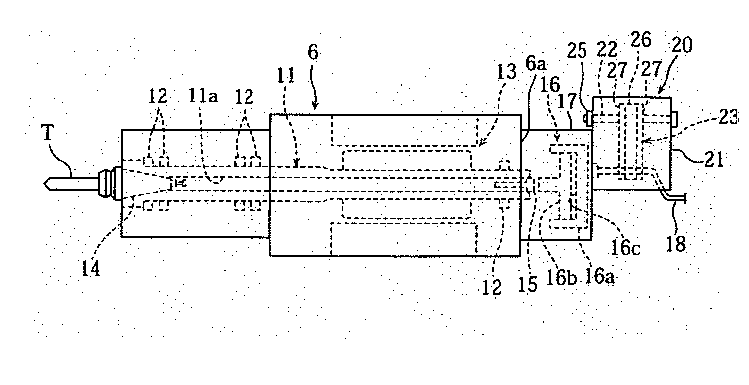
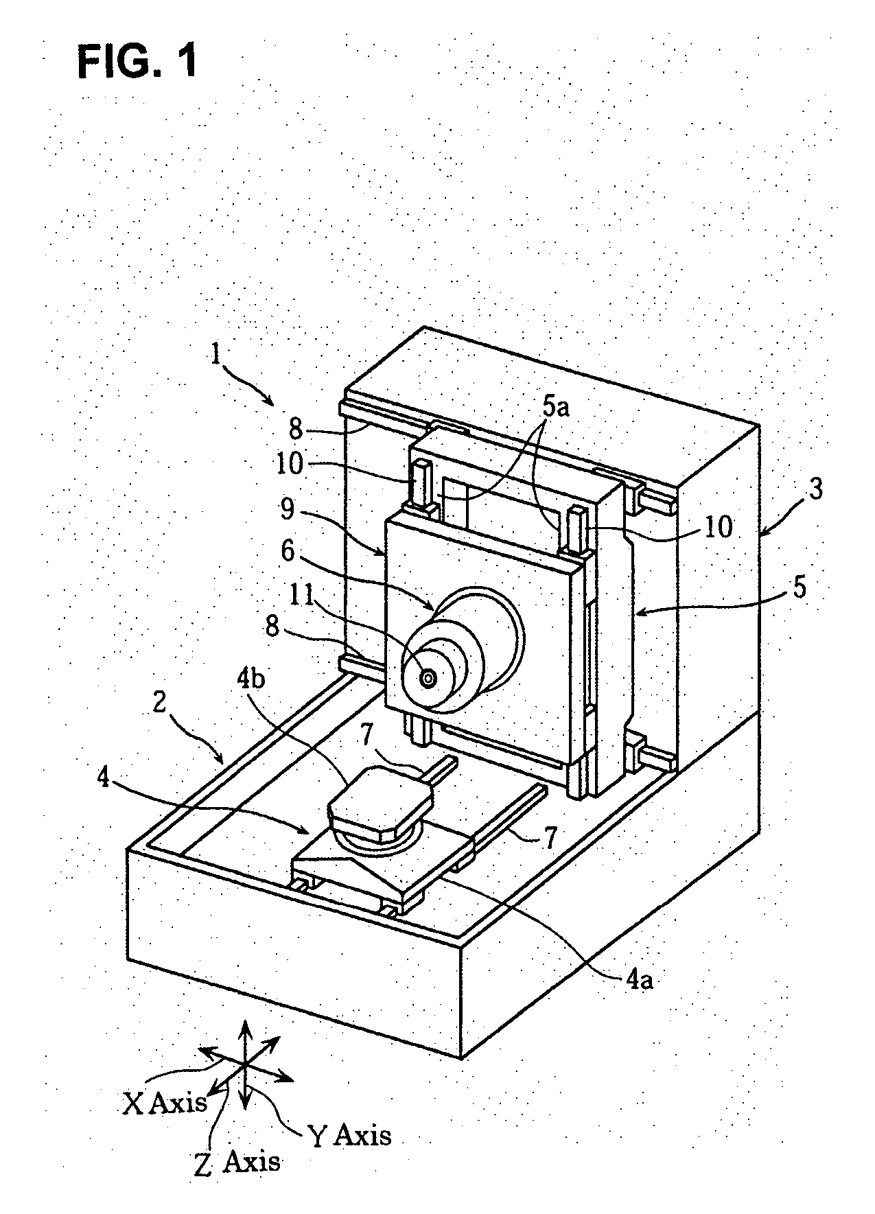
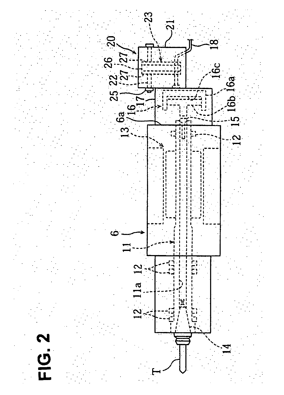
[0023]FIG. 1 to FIG. 4 are views to illustrate a chattering vibration inhibiting mechanism of a machine tool according to the embodiment of the present invention, in which FIG. 1 is a perspective view of the machine tool, FIG. 2 is a side view of a spindle head, FIG. 3 and FIG. 4 are a sectional view and a perspective view, respectively, of the chattering vibration inhibiting mechanism.

[0024] In the drawings, “1” denotes a lateral machining center. A bed 2 of the machining center 1 is rectangular in plan view with an arch-shaped column 3 being disposed and fixed in a standing manner at the rear end portion thereof. A working table 4 is disposed in front of the column 3 in a movable manner in the z-axis (front and rear) direction. A saddle 5 is disposed on the front surface of the column 3 in a movable manner in the x-axis (right and left) direction with a spindle he...


PUM

PropertyMeasurementUnit
Weightaaaaaaaaaa

Abstract

A chattering vibration inhibiting mechanism capable of inhibiting chattering vibration of a machine tool without increasing weight nor requiring a time-consuming adjustment work is provided. A box-shaped package body 21 attached to a spindle head 6, a supporting member 22 disposed to bridge between front and rear walls 21a, 21b in the box-shaped package body 21, and a damper 23 composed of an elastic member 27 and a weight 26 supported by the supporting member 22 are provided.

Description

BACKGROUND OF THE INVENTION [0001] 1. Field of the Invention [0002] The present invention relates to a machine tool provided with a spindle equipped with a tool and a spindle head supporting the spindle in a rotatable manner, and more specifically to, a chattering vibration inhibiting mechanism designed to inhibit chattering vibration generated in machining of a work. [0003] 2. Description of the Related Art [0004] In a machine tool, accuracy in machining of a work possibly degrades due to chattering vibration generated in the machining of the work. In order to inhibit the chattering vibration as described above, for instance, according to Japanese Patent Application Laid-Open No. Sho56-102441, there is one, in which a container accommodating many solid fine particles made of metal particles having a spherical shape or a tip shape is disposed at an irrotational portion in the vicinity of a cutting tool. [0005] Meanwhile, a structure disposing a container accommodating many solid fin...

Claims


Application Information

Patent Timeline
IPC IPC(8): B23Q11/00
CPCY10T409/304312B23Q11/0035B23Q2220/006B23Q5/04B23Q11/00
Inventor HASHIMOTO, KAZUTADAFUKUNAGA, OSAMUHOSHI, TAKASHI
Owner DMG MORI SEIKI CO LTD
Why Eureka
Try Eureka