Automatic surgical device and control assembly for cutting a cornea

a corneal cap and automatic technology, applied in the field of medical devices, can solve the problems of corneal cap loss, eye surgery, eye treatment, etc., and achieve the effects of convenient removal of cutting blades, effective cutting and range of movement, and quick and easy installation and removal

Inactive Publication Date: 2007-10-18
HELLENKAMP JOHANN F
View PDF99 Cites 450 Cited by
  • Summary
  • Abstract
  • Description
  • Claims
  • Application Information

AI Technical Summary

Benefits of technology

[0015] The present invention further comprises a driving assembly for driving the cutting head assembly over the retaining and positioning assembly, and in the preferred embodiment, may include a stop assembly, which is structured and disposed to limit movement of the cutting head assembly across the retaining and positioning assembly. The stop assembly may be formed on the cutting head assembly and may be structured and disposed to engagingly abut a portion of the guide assembly so as to limit further movement of the cutting head assembly at a point before the cutting element has passed completely over the cornea of the eye, thereby forming the corneal flap on the eye undergoing surgery. In the preferred embodiment, the drive assembly is operably connected to the cutting head assembly at a top surface thereof and is capable of stopping and reversing the direction of movement of the cutting head assembly once the stop assembly has prevented movement of the cutting head assembly in a first direction across the retaining and positioning assembly.
[0016] In addition, the present invention is directed towards an improved microkeratome cutting blade assembly that permits quick and easy installation and removal from the microkeratome housing, without excessive manipulation, and which provides an effective cut and range of movement. Preferably, the cutting blade assembly of the present invention is seen to comprise an improved cutting blade and blade holder. The cutting blade comprises a front portion that includes a sharp, forward cutting edge, a rear, trailing portion having a rear edge, and a pair of side edges, at least one of which extends and tapers between the front and rear trailing portions. The cuttin...

Problems solved by technology

Until about twenty years ago, refractive errors of light passing through the eye could only be treated with eyeglasses or contact lens, both of which have well known disadvantages for the user.
The reasons are primarily two-fold: first, the possibility exists that when the corneal cap is put back in place on the cornea, it will not be aligned properly with the remaining corneal tissues, which has several drawbacks for the patient, and second, the possibility exists that the corneal cap will become lost during the surgery, and if that occurs, the consequences for the patient are catastrophic.
This excessive manipulation required of known microkeratome devices is not conducive, however, to maintaining the proper sanitary and sterilized state required for surgery.
Moreover, in manipulating the access means of certain known microkeratome devices, some surgeons have unintentionally caused the cutting blade to become dislodged, or worse, have even bent the cutting blade, thereby requiring the assembly process to start over again.
This factor tends to only exacerbate the problems encountered in the art in that these known blade holding ...

Method used


Image

  • Automatic surgical device and control assembly for cutting a cornea
  • Automatic surgical device and control assembly for cutting a cornea
  • Automatic surgical device and control assembly for cutting a cornea

Examples


Embodiment Construction

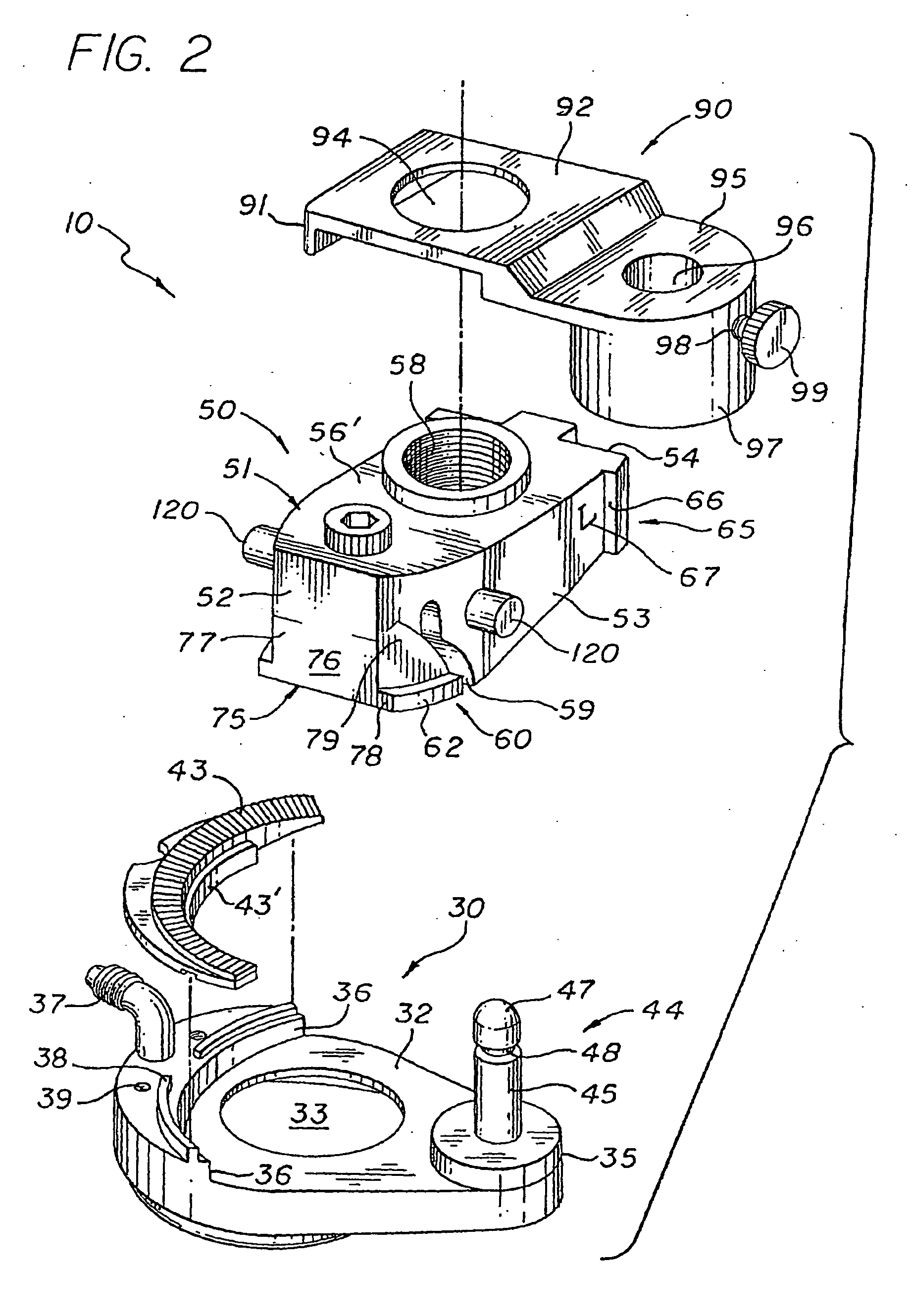
[0037] As illustrated throughout the Figures, the present invention is directed towards an improved automatic microkeratome device for smoothly cutting the cornea of an eye, generally indicated by reference numeral 10, and towards a cutting blade assembly therefor, generally indicated by reference numeral 105, and towards a control assembly therefor, generally indicated by reference numeral 200.

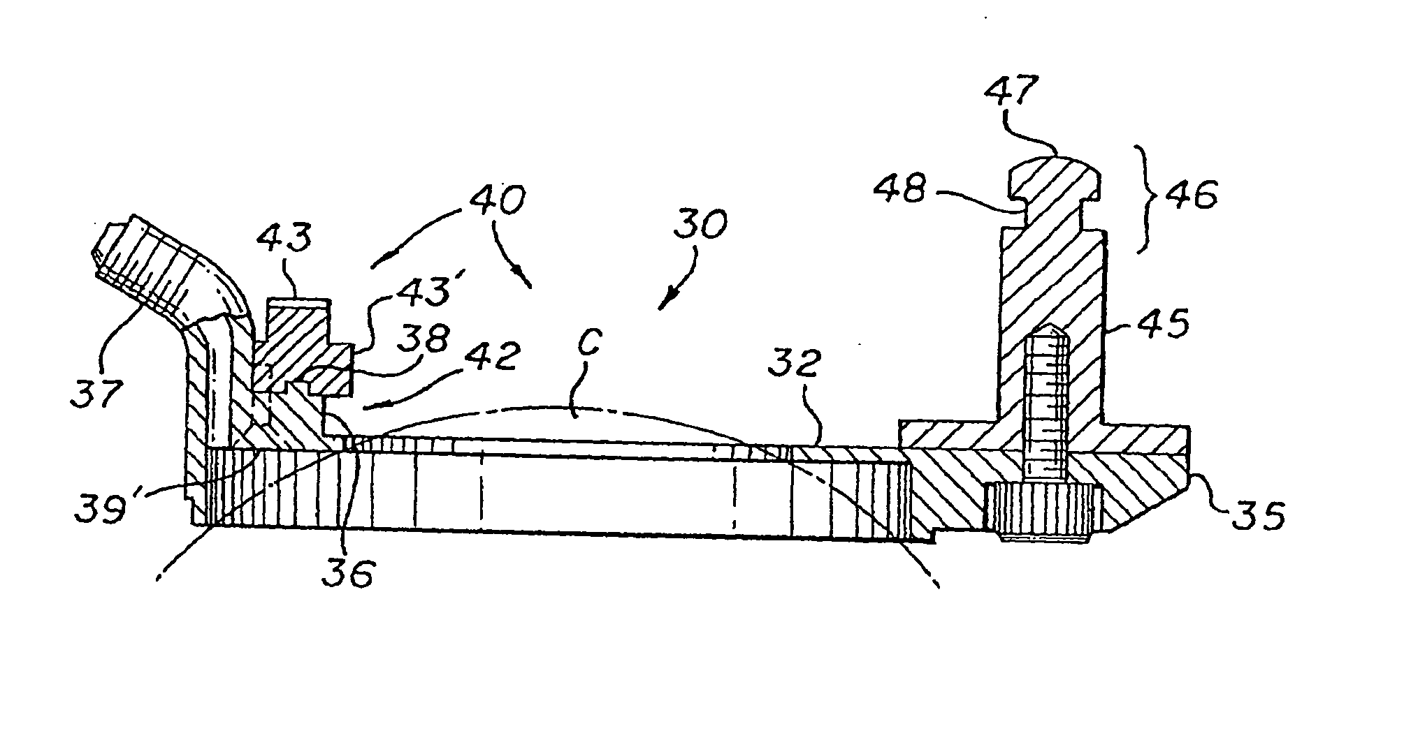
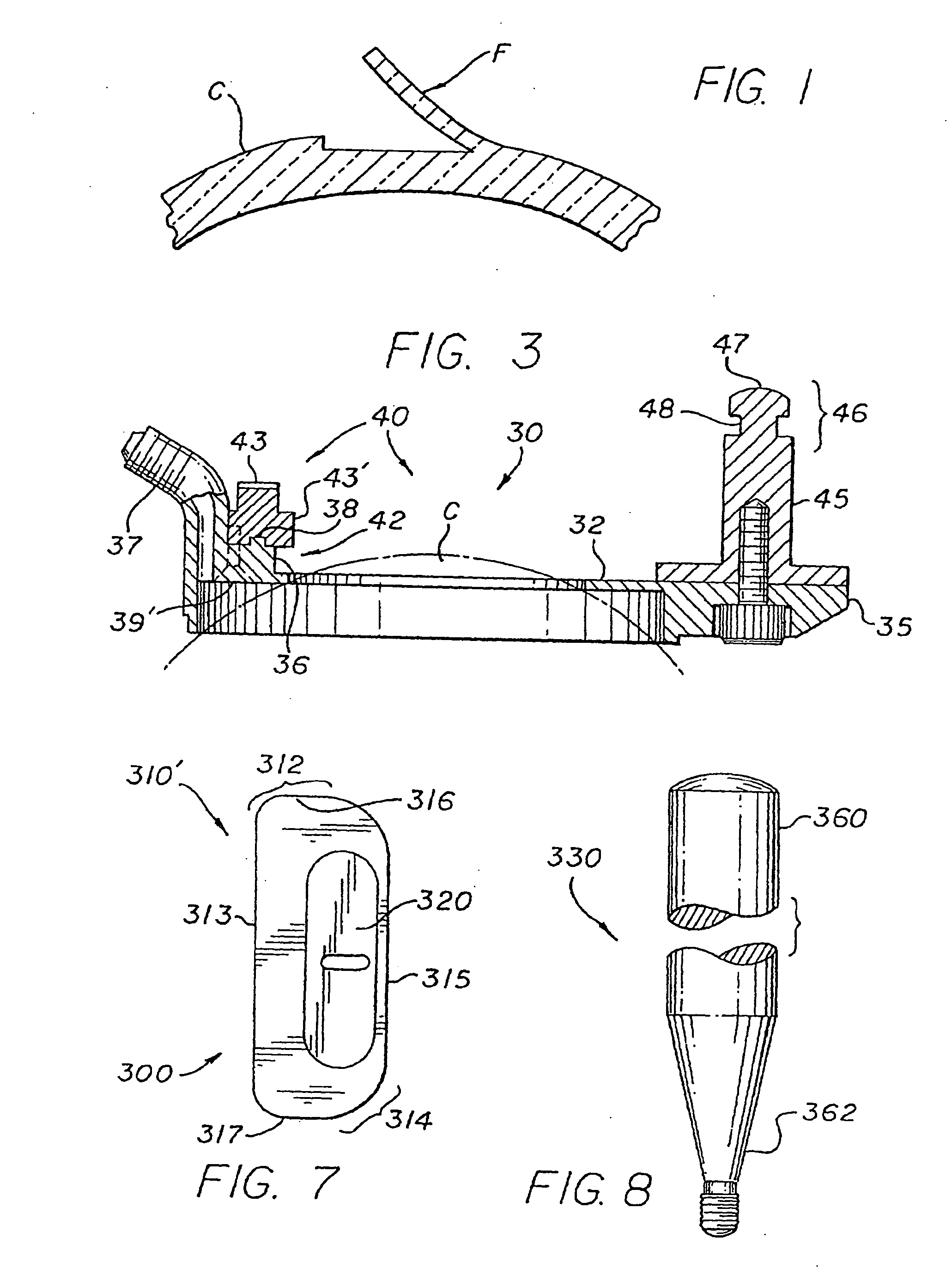
[0038] The preferred and improved automatic microkeratome device of the present invention, which is structured to cut substantially but not completely across the cornea of a patient's eye so as to raise a thin layer thereof and create a hinged flap of corneal tissue, will be discussed first. As illustrated in FIGS. 2 and 3, the preferred microkeratome device 10 includes means 30 for retaining and positioning the eye on which surgery is to be performed. The retaining and positioning means 30, which may be made of high grade stainless steel, preferably comprise a positioning ring 32 having an ...


PUM


Abstract

A surgical device for cutting substantially across a cornea of an eye of a patient, the device including a positioning ring to be attached to an eye surrounding a cornea to be cut, and defining an aperture sized to receive and expose the cornea to be cut. The surgical device further includes a cutting head assembly structured to be guided and driven over an upper surface of the positioning ring in a generally arcuate path, and having a cutting element positioned therein and structured to oscillate laterally to facilitate smooth and effective cutting of the cornea. The cutting head assembly is structured to be detachably coupled to the positioning ring by a coupling member which permits movement of the cutting head assembly relative to the positioning ring along the generally arcuate path, but maintains sufficient engagement therebetween to ensure that smooth, steady, driven movement is maintained.

Description

CLAIM OF PRIORITY [0001] The present application is a continuation-in-part of and claims priority to the following applications and / or issued patents, each of which is incorporated fully herein by reference: U.S. patent application having Ser. No. 10 / 062,178 filed Jan. 31, 2002, also incorporated herein by reference, which matured into U.S. Pat. No. 7,166,117 on Jan. 23, 2007 which is a continuation-in-part of U.S. patent application having Ser. No. 09 / 841,165 filed Apr. 24, 2001, now abandoned which is a continuation of an earlier filed U.S. patent application, namely Ser. No. 08 / 840,430 filed on Apr. 29, 1997 which matured into U.S. Pat. No. 6,296,649 on Oct. 2, 2001, which itself was a continuing application based on that U.S. patent application filed on Feb. 7, 1996 and assigned Ser. No. 08 / 598,180 which matured into U.S. Pat. No. 5,624,456 on Apr. 29, 1997. The present application also claims priority to and is a continuation-in-part of the following, each also incorporated ful...

Claims


Application Information

Patent Timeline
IPC IPC(8): A61F9/007A61F9/013
CPCA61F9/013
Inventor HELLENKAMP, JOHANN F.
Owner HELLENKAMP JOHANN F
Why Eureka
Try Eureka