Drain outlet with integral clamp for use with a plumbing fixture

a technology of plumbing fixtures and drain outlets, which is applied in water installations, washstands, constructions, etc., can solve the problems of affecting the appearance of the drain flange, affecting the cleaning effect of the lavatory, and being difficult to completely clean, etc., and achieves the effects of convenient cleaning, easy assembly, and low manufacturing cos

Inactive Publication Date: 2007-10-25
KOHLER CO
View PDF25 Cites 0 Cited by
  • Summary
  • Abstract
  • Description
  • Claims
  • Application Information

AI Technical Summary

Benefits of technology

[0017]The present invention is inexpensive to manufacture, and can be assembled quite quickly. Further, it is intuitive in its nature, making it suitable for use by those without formal plumbing training.
[0018]Importantly, no drain flange is required on the visible portion of the lavatory basin. As a result, apart from the ornamental improvement which results, the design also does not require an additional sealing step along the top surface of the lavatory basin. Further, the basin is somewhat easier to clean.

Problems solved by technology

In any event these designs leave an exposed, typically metal, drain flange visible to the user.
For one thing, the drain flange disrupts the ornamentation on the surface of the lavatory if the lavatory surface has been ornamented.
For another, the point at which the edge of the flange contacts the lavatory basin top surface is a location which can be somewhat difficult to completely clean.
Further, the greater number of parts required, the greater the manufacturing cost, and the greater the cost of assembly if a plumber is hired to make the assembly.

Method used


Image

  • Drain outlet with integral clamp for use with a plumbing fixture
  • Drain outlet with integral clamp for use with a plumbing fixture
  • Drain outlet with integral clamp for use with a plumbing fixture

Examples


Embodiment Construction

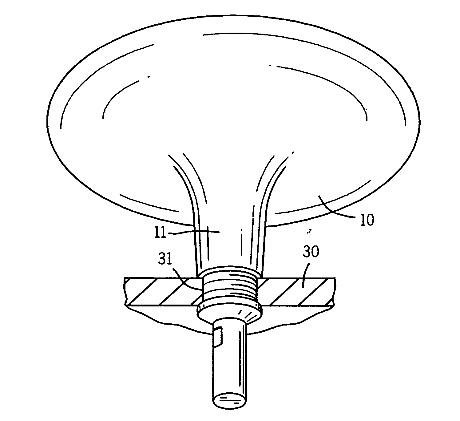
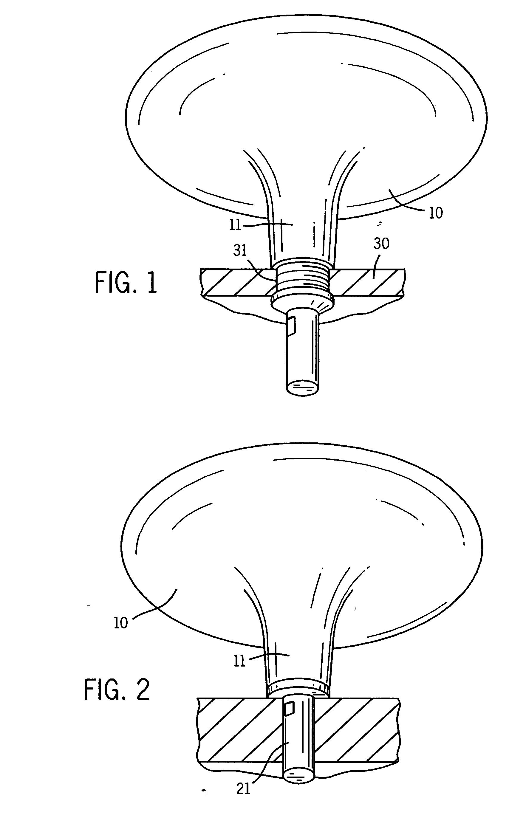
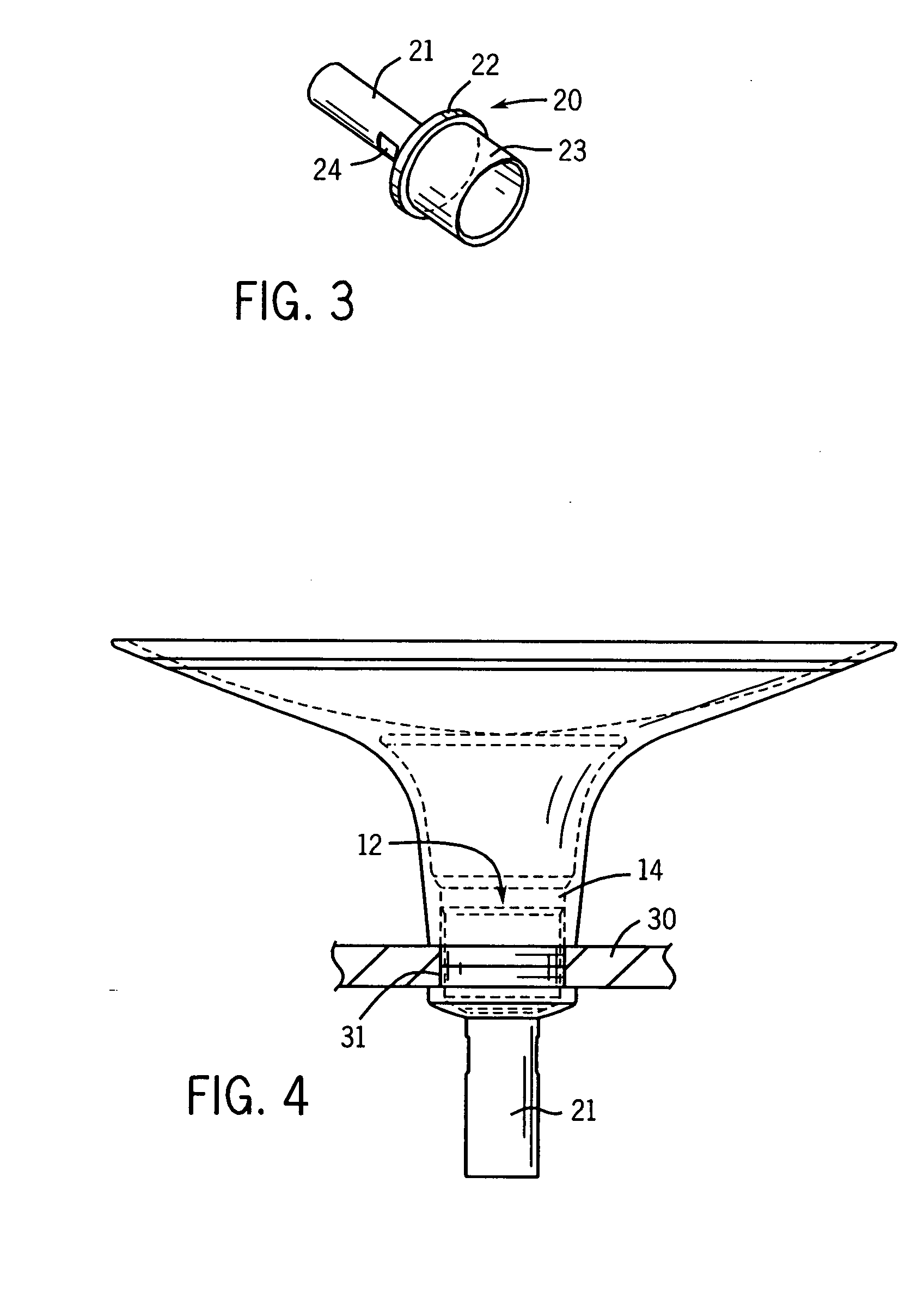
[0024]Referring first to FIGS. 1 and 2, there is shown a lavatory 10 having a lower drain outlet portion 11. That lower portion 11 is provided with a cylindrical vertical drain bore 12 which is internally threaded at 14. The entire lavatory 10 can be an integral one-piece structure made of a machinable metal such as brass. There is no need for a drain flange that is visible from the top of the design one the lavatory is installed.

[0025]FIG. 3 depicts a drain structure 20 having a drain tube portion 21, a clamping flange 22 and an outwardly threaded enlarged tubular portion 23. There is also a flat 24.

[0026]When the lavatory 10 is to be mounted in a clamping installation like that of FIG. 1, the lavatory 10 can be positioned on a counter top 30 or the like having a through bore 31. The threaded portion 23 of the drain structure 20 can then be partially threaded into the threads 14 until the flange 22 abuts under the counter top 30 to affix / clamp the lavatory in place.

[0027]If desired...


PUM


Abstract

A drain tube assembly for use with a lavatory or other plumbing fixture is disclosed. The lavatory has a basin, a lower drain outlet having an internal threaded bore, and a one-piece drain structure having a drain tube adjacent one axial end, an attachment sleeve adjacent an opposed axial end which is radially outwardly threaded, and a radially extending flange there between. When attached, the drain structure has an axial path extending through the attachment sleeve, flange, and drain tube to carry liquid from the lavatory out the drain tube. In a first position the flange can form a clamp member if the assembly is to be mounted through a counter top. Alternatively the flange can in a second position form a base for the lavatory when the lavatory is suspended. Movement between the positions is created by varied degrees of threading the sleeve into the lower drain.

Description

CROSS-REFERENCE TO RELATED APPLICATION[0001]This application claims priority of provisional application 60 / 793,687 dated Apr. 20, 2006.STATEMENT OF FEDERALLY SPONSORED RESEARCH OR DEVELOPMENT[0002]Not applicable.BACKGROUND OF THE INVENTION[0003]The present invention relates to lavatories and other plumbing fixtures which have a drain outlet. It particularly relates to an attachable drain with an integral clamping flange that can be adjustably fixed to the plumbing fixture to facilitate varied types of installations.[0004]U.S. Pat. No. 6,367,102 shows a prior art type of lavatory installation where there is a drain hole through the bottom of the lavatory basin. In this assembly a drain flange is positioned in the basin around the drain hole and also partially in the drain hole. The flange has a lower threaded end.[0005]That lower end is then linked below the counter top to a drain tube which, in the case of this patent, has an integral clamping flange. Tightening the drain tube onto ...

Claims


Application Information

Patent Timeline
Patent Type & Authority Applications(United States)
IPC IPC(8): E03C1/00A47K1/04
CPCE03C1/32E03C1/22
Inventor MCMULLEN, MARK F.
Owner KOHLER CO
Why Eureka
Try Eureka