Global rack system

Inactive Publication Date: 2007-10-25
SANMINA-SCI CORPORATION
View PDF22 Cites 10 Cited by
  • Summary
  • Abstract
  • Description
  • Claims
  • Application Information

AI Technical Summary

Benefits of technology

[0013] In another preferred embodiment, the rack further includes four casters mounted on four corners of the base frame to support the rack and facilitate movement of the rack. The rack may further include locating plates attached to the horizontal members at places where t

Problems solved by technology

It is possible to make an equipment rack that is strong enough to avoid these damages by using heavier material and more bracing members, but this adds si

Method used


Image

  • Global rack system
  • Global rack system
  • Global rack system

Examples


Example

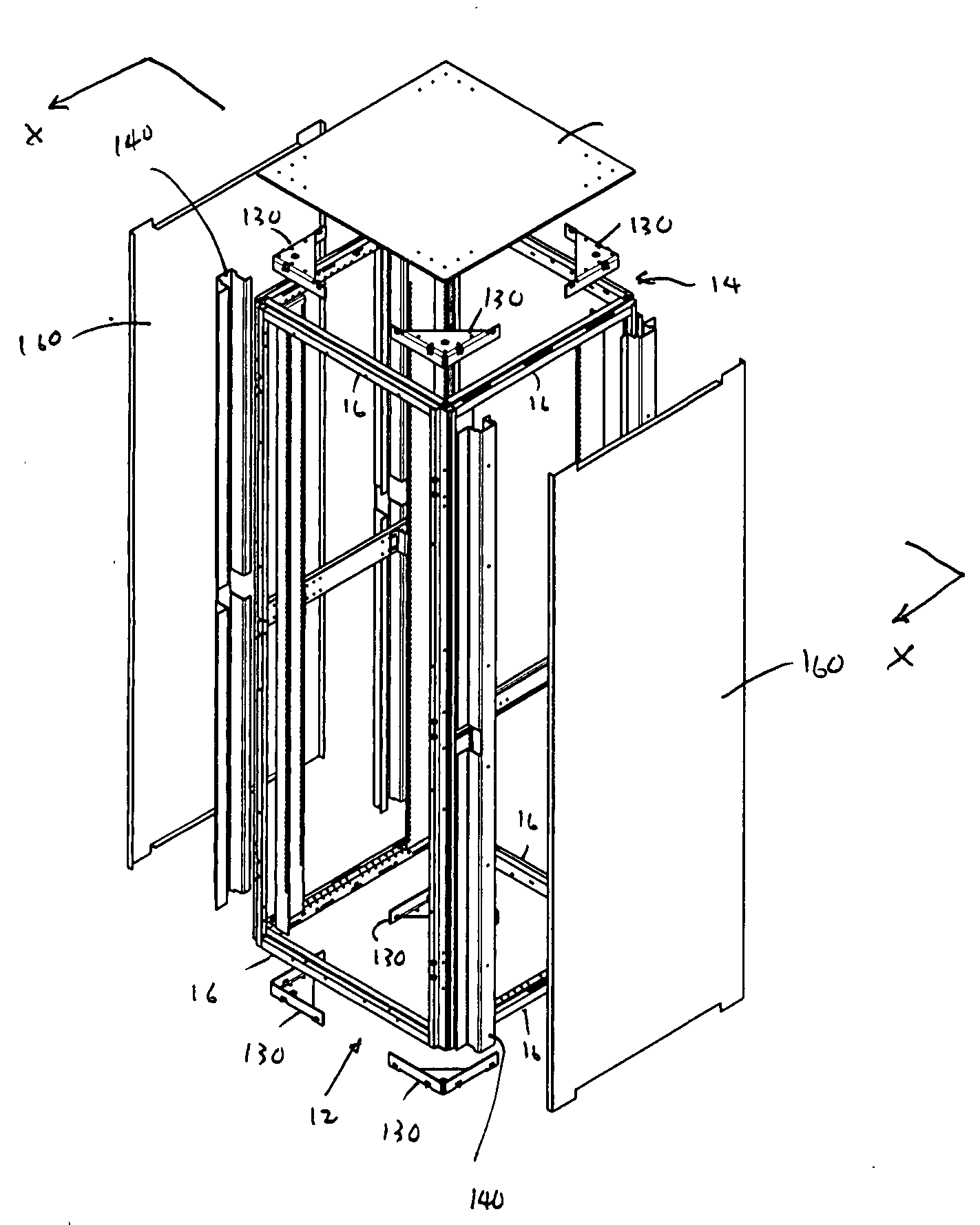
[0035] The present invention provides a new and improved electronic equipment rack system including features that provide the rack with exceptional strength and rigidity without substantially increasing the weight and cost of the rack. The rack system, in accordance with one preferred embodiment, generally includes a box-like frame, a door mounted to the front of the frame, a back door or panel and two side panels mounted to the back and two sides of the frame, and a roof panel mounted to the top of the frame.

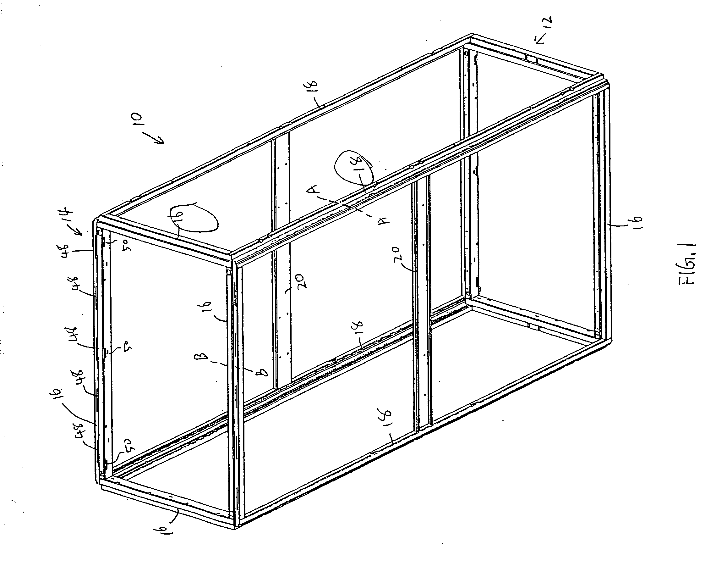
[0036] Referring to FIG. 1, the frame of the rack system 10 generally includes a rectangular base frame 12 constructed by four horizontal edge members 16, and a top frame 14 having the same structure as the base frame 12, and four vertical members 18 each extending between two associate corners of the base frame 12 and the top frame 14, and joining the base frame 12 and top frame 14 together. The base frame 12, top frame 14, and the four vertical members 18 form the elongated ...


PUM


Abstract

A rack system for electronic and/or electrical equipment including a frame, a front door mounted to the front of the frame, a back door or panel, two side panels mounted to the back and two sides of the frame, and a top panel mounted to the top of the frame. The doors can be single doors or dual doors. The frame includes a rectangular base frame constructed by four horizontal edge members, and a top frame having the same structure as the base frame, and four vertical members each extending between two associate corners of the base frame and the top frame, and joining the base frame and top frame together. The horizontal members and vertical members are contoured with step-like structures, so that the rack has a high stiffness and strength. The door includes a hinge and a latch attached to two vertical members. The panels are provided with tabs and latches for securing the panels to the frame.

Description

CROSS REFERENCES TO RELATED APPLICATIONS [0001] This application is a continuation-in-part and claims priority to PCT international application PCT / US2004 / 017351, filed Jun. 1, 2004, which claims priority to U.S. Provisional Application ser. No. 60 / 474,561 filed May 20, 2003, each of which applications is expressly incorporated herein by reference.FIELD OF THE INVENTION [0002] The present invention relates to racks for electronic and / or electrical equipment and, more particularly, to racks having high stiffness and strength. BACKGROUND OF THE INVENTION [0003] A common use of equipment racks of the type to which the present invention relates is for containing electronic or electrical equipment in the racks. In general, the rack has a box-like shape, including a base, side members extending upwardly from the base, and a top mounted to the top ends of the side members. The base, top, and side members form an enclosure within which the electronic or electrical equipment is disposed. [00...

Claims


Application Information

Patent Timeline
IPC IPC(8): H05K5/00
CPCG11B33/02H05K7/183H02B1/013H02B1/01
Inventor HUDZ, ANDREWJEFFERY, PETERSHARIFF, ZIAAAPRO, EINO A.
Owner SANMINA-SCI CORPORATION
Why Eureka
Try Eureka