Vehicle-use power generation control apparatus

a technology of power generation control and vehicle, which is applied in the direction of generator control by field variation, electric generator control, dynamo-electric converter control, etc., can solve the problems of overdischarge of vehicle batteries, inability to prevent large variations in output voltage of vehicle generators, and inability to suppress

Inactive Publication Date: 2007-10-25
DENSO CORP
View PDF8 Cites 20 Cited by
  • Summary
  • Abstract
  • Description
  • Claims
  • Application Information

AI Technical Summary

Benefits of technology

[0024]The rotation detecting circuit may be configured to detect the decrease of the rotational speed in which effect of rotational pulsation depending on an engine combustion cycle of the vehicle engine is reduced.
[0025]The rotation detecting circuit may be configured to detect the decrease of the rotational speed in only effect of rotational pulsation depending on an engine combustion cycle of the vehicle engine.

Problems solved by technology

The former technique as disclosed in Japanese Patent Application Laid-open No. 58-217743, in which decrease or increase of the excitation current is determined on the basis of only the timing of decrease or increase of the engine rotational speed, has a problem in that although the rotational speed variation of the vehicle engine can be suppressed, a variation of an output voltage of the vehicle generator cannot be prevent from becoming large, because this technique does not take the output voltage variation of the vehicle generator into account.
This can causes overcharge or overdischarge of a vehicle battery charged by the vehicle generator.
The latter technique as disclosed in Japanese Patent Application Laid-open No. 2003-284257 has a problem in that although the idle speed variation of the vehicle engine can be suppressed if it is due to the power generation torque variation of the vehicle generator, it cannot be suppressed if it is due to factors other than the power generation torque variation of the vehicle generator.

Method used


Image

  • Vehicle-use power generation control apparatus
  • Vehicle-use power generation control apparatus
  • Vehicle-use power generation control apparatus

Examples


Embodiment Construction

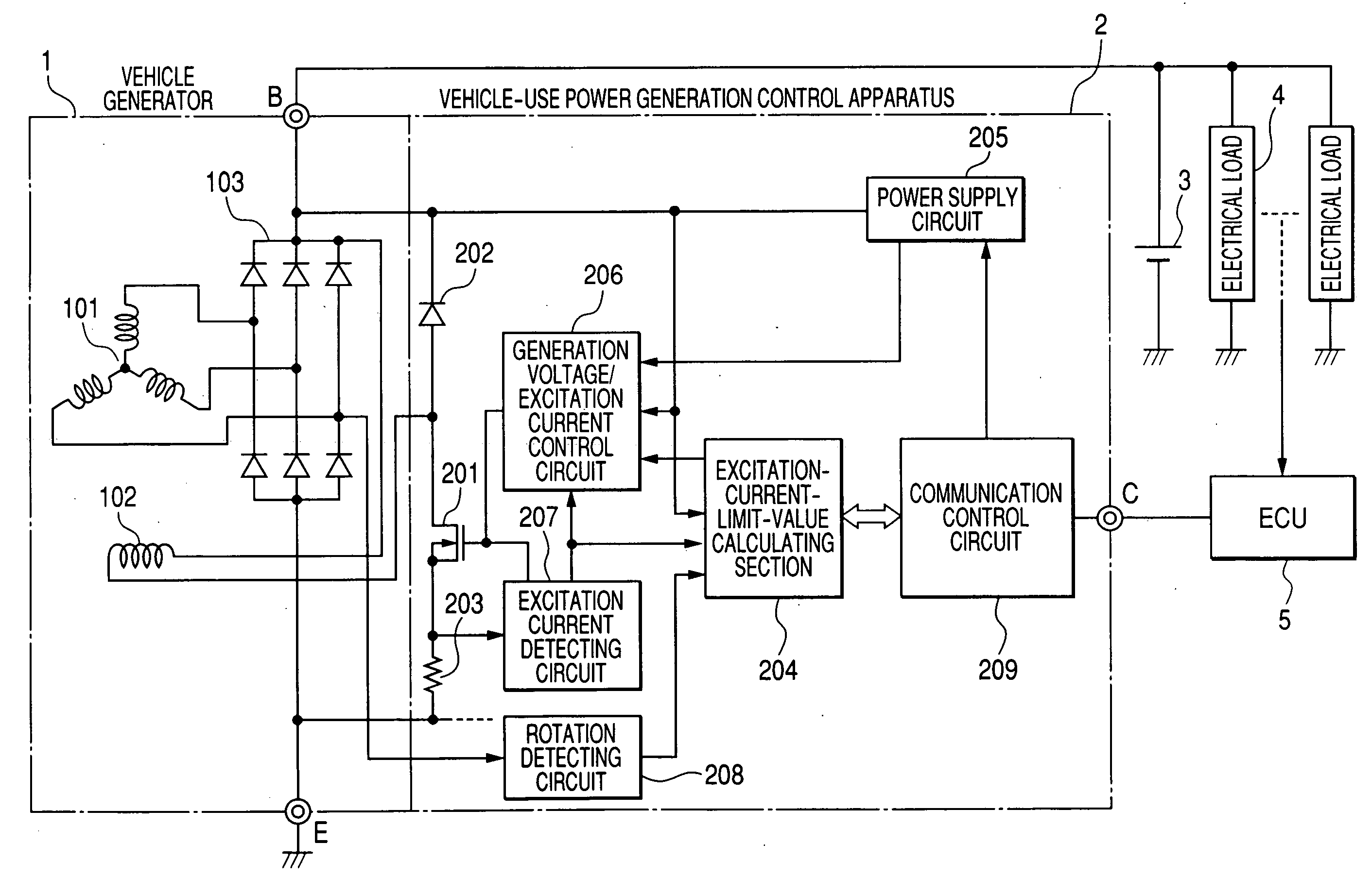
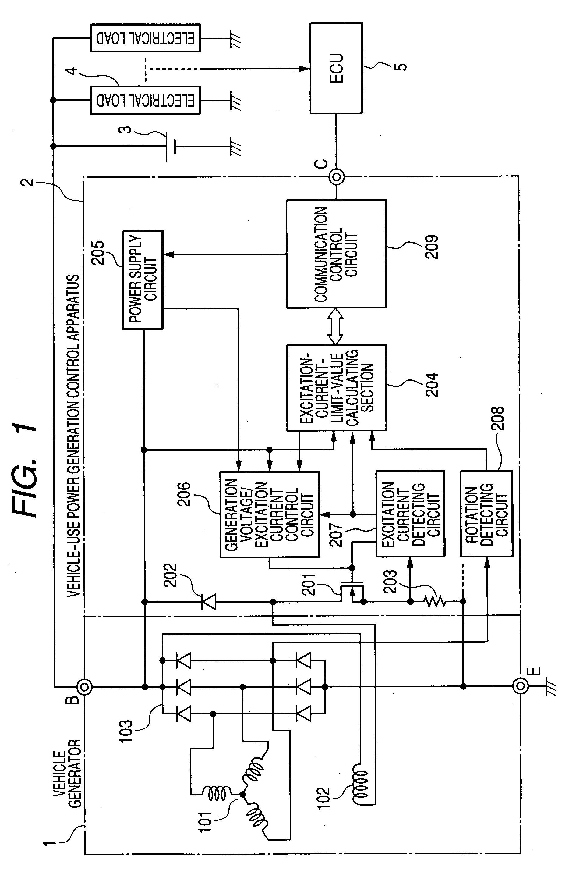
[0039]FIG. 1 is a diagram showing a structure of a vehicle-use power generation control apparatus 2 according to a first embodiment of the invention, which is connected to a vehicle generator 1, a vehicle battery 3, electrical loads 4, and an ECU (Electronic Control Unit) 5.

[0040]The vehicle-use power generation control apparatus 2 operates to keep a voltage at an output terminal (B-terminal) of the vehicle generator 1 at a predetermined target regulation voltage (14V, for example). The vehicle-use power generation control apparatus 2 is provided with a communication terminal (C-terminal), and a ground terminal (E-terminal) in addition to the B-terminal. The B-terminal is connected to the battery 3 and to the electrical loads 4 through a charge line. The C-terminal is connected to the ECU 5 as an external control device. The E-terminal is connected to a frame of the vehicle generator 2. Although the vehicle-use power generation control apparatus 2 is shown as being disposed side by ...


PUM


Abstract

The vehicle-use power generation control apparatus regulates an output voltage of a vehicle generator driven by a vehicle engine at a set value by on/off controlling an excitation current flowing through an excitation winding of the vehicle generator The vehicle-use power generation control apparatus includes a rotation detecting circuit detecting a rotational speed of the vehicle generator, and an excitation current control circuit reducing, when the rotation detecting circuit detects decrease of the rotational speed, the excitation current at a rate depending on a rate of the decrease of the rotational speed detected by the rotation detecting circuit.

Description

CROSS-REFERENCE TO RELATED APPLICATION[0001]This application is related to Japanese Patent Application No. 2006-117869 filed on Apr. 21, 2006, the contents of which are hereby incorporated by reference.BACKGROUND OF THE INVENTION[0002]1. Field of the Invention[0003]The present invention relates to a vehicle-use power generation control apparatus for controlling a power generating operation of a generator mounted on a vehicle such as a passenger car or a truck.[0004]2. Description of Related Art[0005]There is known a technique in which, in order to reduce variation of a rotational speed of a vehicle engine depending on its combustion cycle when the vehicle engine is in an idle state, a power generation torque control is performed such that an excitation current of a vehicle generator driven by the vehicle engine is decreased to decrease a power generation torque of the vehicle generator at the timing when the engine rotational speed decreases, and the excitation current is increased ...

Claims


Application Information

Patent Timeline
Patent Type & Authority Applications(United States)
IPC IPC(8): H02H7/06H02P9/00H02P11/00
CPCH02J7/244H02P2101/45H02P9/30H02J7/243
Inventor MAEHARA, FUYUKI
Owner DENSO CORP
Why Eureka
Try Eureka