Noise reduction apparatus of frame recursive type

a noise reduction and frame recursive technology, applied in the field of image signal noise reduction, can solve the problems of low image quality, motion detector b>105/b> can fail to detect the motion amount, blurring or trailing the contour of the motion image, etc., and achieve the effect of reducing noise in the input image signal and reducing noise in the differential image signal

Inactive Publication Date: 2007-10-25
PIONEER CORP
View PDF7 Cites 8 Cited by
  • Summary
  • Abstract
  • Description
  • Claims
  • Application Information

AI Technical Summary

Benefits of technology

[0013] According to a third aspect of the present invention, there is provided a noise reduction apparatus of a frame recursive type which reduces noise in an input image signal. The noise reduction apparatus comprises: a frame recursive type filter for generating a differential image signal representing a difference between a current input image signal and a delayed image signal that is obtained by delaying the input image signal by at least one frame period, reducing noise in the differential image signal thereby to generate a feedback image signal, and adding the feedback image signal to the current input image signal; a hue analyzer for measuring a hue angle on the basis of a color difference component of the input image signal; and a level adjuster for adjusting a level of the feedback image signal to a lower level as the measured hue angle is nearer to a predetermined angle.

Problems solved by technology

However, when the effect of reducing the noise is enhanced, an afterimage phenomenon such as blurring or trailing of the contour of the motion image occurs and lowers image quality.
Particularly, when the difference between the image frames is small, the motion detector 105 can fail in detection of the motion amount.
In this case, the recursive factor setting unit 106 cannot set a recursive factor with respect to the delayed image signal to a proper value, thus causing blurring or trailing of the contour of the motion image to occur.

Method used


Image

  • Noise reduction apparatus of frame recursive type
  • Noise reduction apparatus of frame recursive type
  • Noise reduction apparatus of frame recursive type

Examples


first embodiment

1. First Embodiment

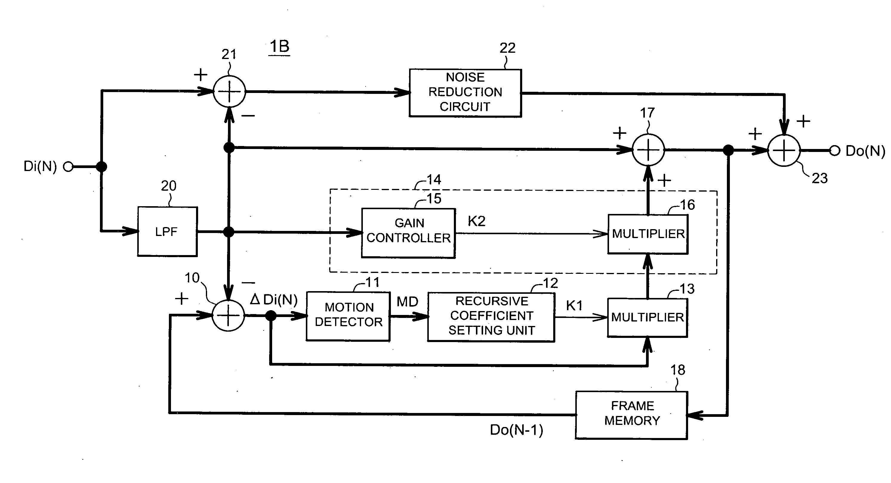
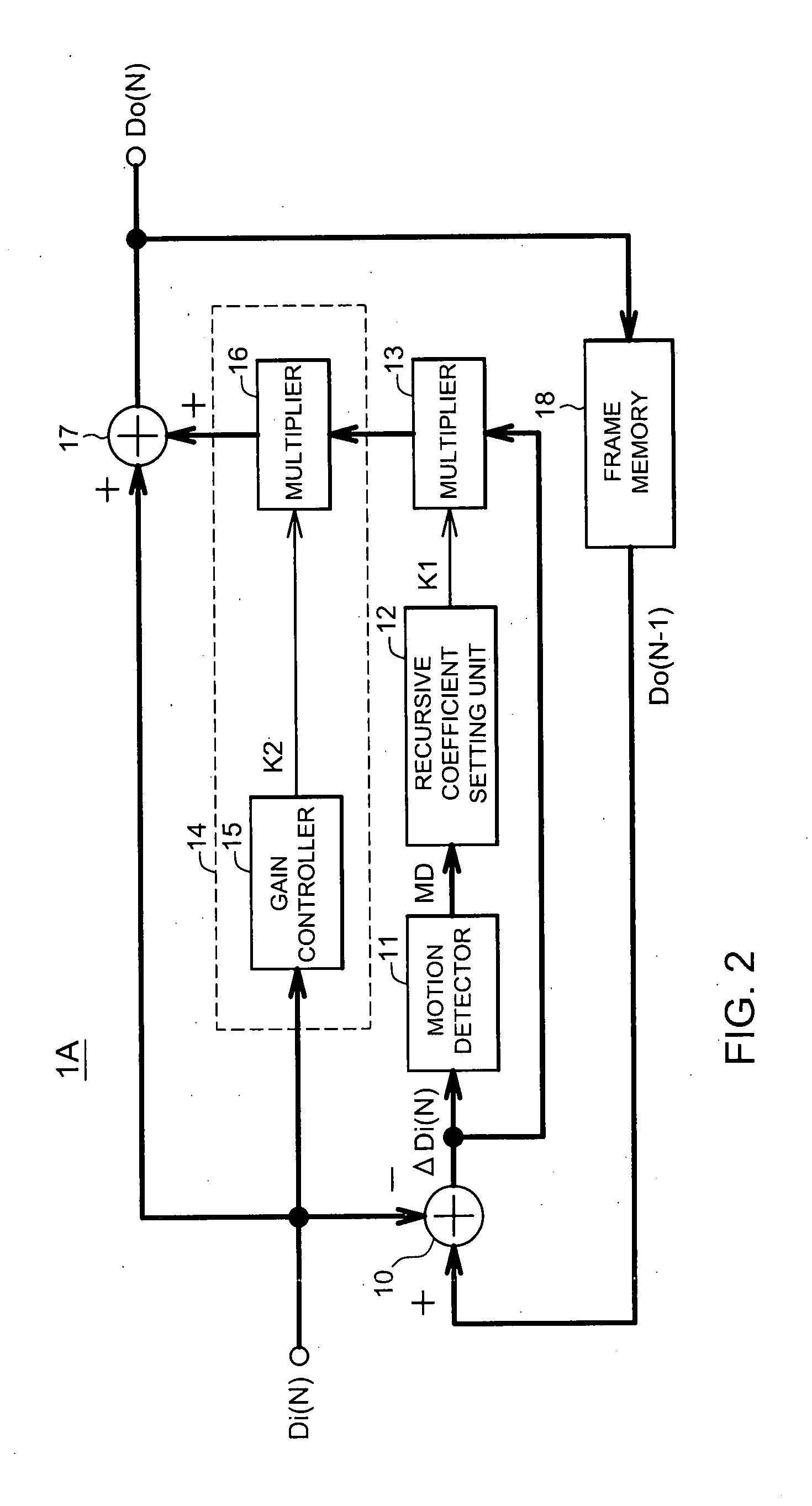
[0028]FIG. 2 is a functional block diagram showing a schematic configuration of a noise reduction apparatus 1A of the frame recursive type according to a first embodiment of the present invention. This noise reduction apparatus 1A has a subtracter 10, a motion detector 11, a recursive coefficient setting unit 12, a first multiplier 13, an adder 17 and a frame memory 18. “A frame recursive type filter” can be constructed by these functional blocks 10, 11, 12, 13, 17 and 18. The noise reduction apparatus 1A further has a level adjuster 14 for adjusting the level of a feedback image signal which is an output signal of the first multiplier 13.

[0029] First, an operation of the frame recursive type filter will be described. An input image signal Di(N) is a digital image signal such as a luminance signal (Y signal), color difference signals (Cb signal and Cr signal), a primary color signal (R signal, G signal and B signal) or the like, for example. The input image signa...

second embodiment

2. Second Embodiment

[0038] A second embodiment of the present invention will be described. FIG. 5 is a functional block diagram showing a schematic configuration of a noise reduction apparatus 1c of the frame recursive type according to the second embodiment. The components designated by the same reference numeral in FIGS. 2 and 5 have the same function, and thus the detailed description of the components is omitted. As described above, the afterimage phenomenon such as blurring or trailing of the contours of the motion images is conspicuous due to the low-band component of the input image signal Di(N). Thus, it is necessary to suppress the noise reduction processing for the low-band component of the input image signal Di(N).

[0039] A configuration of the noise reduction apparatus 1C according to the second embodiment includes a frequency analyzer 30 and a level adjuster 31. In this respect, the configuration of the noise reduction apparatus 1C is different from the configuration of...

third embodiment

3. Third Embodiment

[0044] A third embodiment of the present invention will be described. FIG. 7 is a functional block diagram showing a schematic configuration of a noise reduction apparatus 1D of the frame recursive type according to the third embodiment. The components designated by the same reference in FIGS. 7 and 2 have the same function, and thus the detailed description of the components is omitted.

[0045] The configuration of the noise reduction apparatus 1D according to the third embodiment includes a hue analyzer 40 and a level adjuster 41. In this respect, the configuration of the noise reduction apparatus 1D is different from the configuration of the noise reduction apparatus 1A according to the first embodiment, and nevertheless has the same basic configuration of the noise reduction apparatus 1A. The hue analyzer 40 includes a hue analyzer 40 that measures a hue angle of the input image signal Di(N) based on color difference signals (Cr data and Cb data) of the input i...


PUM


Abstract

Disclosed is a noise reduction apparatus of a frame recursive type which can reduce occurrence of an afterimage phenomenon such as blurring or trailing of contours of motion images even when the difference between image frames is small. In the noise reduction apparatus, a frame recursive type filter generates a differential image signal representing a difference between a current input image signal and a delayed image signal obtained by delaying the input image signal by at least one frame period, reduces noise in the differential image signal thereby to generate a feedback image signal, and adds the feedback image signal to the current input image signal. A level adjuster adjusts a level of the feedback image signal to a lower level as a level of a luminance or color component of the input image signal is decreased.

Description

BACKGROUND OF THE INVENTION [0001] 1. Field of the Invention [0002] The present invention relates to a technique for reducing noise in an image signal. [0003] 2. Description of the Related Art [0004] In motion images, there is usually strong correlation between image frames that are sequentially ordered in time. There is further a known fact that correlation is very low between noise components contained in the image frames that are sequentially ordered in time. As a technique for reducing the noise based on that known fact, a noise reduction technique of a frame recursive type is known. [0005]FIG. 1 is a diagram showing a schematic configuration of a conventional noise reduction apparatus 100 of the frame recursive type. In this noise reduction apparatus 100, an input image signal is a digital image signal such as a luminance signal (Y signal), color-difference signals (Cb signal and Cr signal), primary color signals (R signal, G signal and B signal) or the like. A multiplier 101 m...

Claims


Application Information

Patent Timeline
Patent Type & Authority Applications(United States)
IPC IPC(8): H04N5/00G09G3/20G09G5/00H04N5/21
CPCG06T2207/10016H04N5/21G06T2207/10024G06T5/002G06T5/50H04N9/646
Inventor OKUMICHI, KENJIKAWAGUCHI, HIROFUMI
Owner PIONEER CORP
Why Eureka
Try Eureka