Micron grating accelerometer testing method based on added mass

An accelerometer and additional mass technology, applied in the direction of speed/acceleration/shock measurement, test/calibration of speed/acceleration/shock measurement equipment, measurement device, etc. Problems such as rotational stability, complex structure and test methods, etc., can improve the test environment, shorten the development time, and improve the test efficiency.

Active Publication Date: 2015-06-10
BEIHANG UNIV
View PDF4 Cites 0 Cited by
  • Summary
  • Abstract
  • Description
  • Claims
  • Application Information

AI Technical Summary

Problems solved by technology

However, it is difficult to accurately measure the working radius from the rotation axis of the centrifuge to the center of mass of the accelerometer, and the centrifuge is required to have a large size and high rotational stability under high g acceleration, which will lead to further complexity of the structure and test methods, which is not conducive to the acceleration real-time batch online testing, resulting in extended product development time
The equipment for testing at the same time is expensive, and the requirements for the test conditions are harsh, which are generally not easy to meet

Method used


Image

  • Micron grating accelerometer testing method based on added mass
  • Micron grating accelerometer testing method based on added mass
  • Micron grating accelerometer testing method based on added mass

Examples


Embodiment Construction

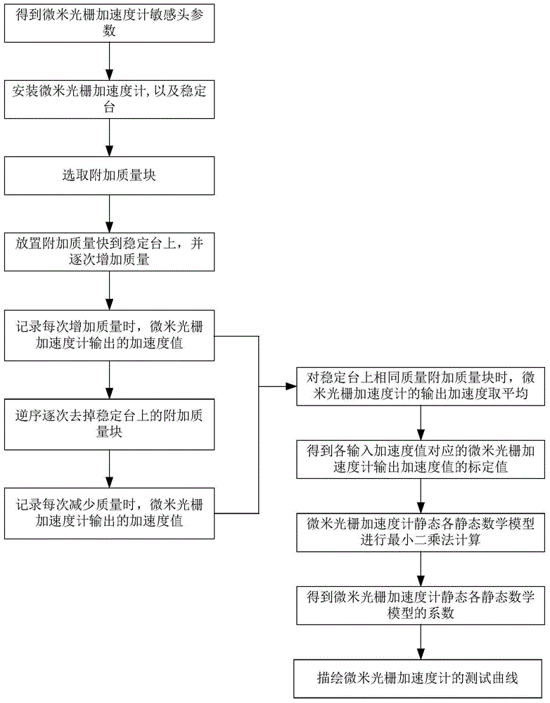
[0031] A kind of micron grating accelerometer testing method based on additional quality of the present invention, such as image 3 As shown, it is realized through the following steps:

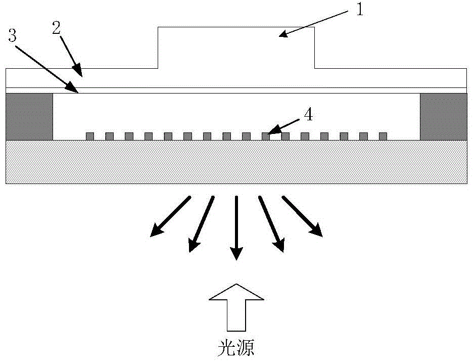
[0032] Step 1: Through theoretical calculation and simulation analysis, obtain the detectable input acceleration range of the micron grating accelerometer sensitive head, the elastic coefficient of the cantilever beam, the damping and the mass of the central mass and other sensitive head parameters.

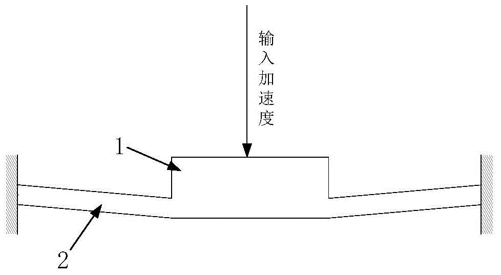
[0033] Step 2: Install the sensitive head of the micron grating accelerometer on the test table, and at the same time install the stable platform on the central mass of the micron grating accelerometer, such as Figure 4 shown. In the present invention, guide holes are evenly opened in the circumferential direction of the stabilizing platform, and guide posts are inserted into the guiding holes as guide rails for the stabilizing platform to move up and down, so that the stabilizing platform onl...


PUM


Abstract

The invention discloses a micron grating accelerometer testing method based on added mass. The method includes firstly, acquiring sensing head parameters by theoretical calculation and simulation analysis; mounting an accelerometer sensing head on a testing table, and arranging a stabilizing table on the upper surface of an accelerometer central mass; then selecting the mass, number and total weight of added masses; placing the added masses on the stabilizing table sequentially, and allowing the accelerometer to increase inputted acceleration values from 0 g to the upper range of accelerometer measurements gradually; removing the added masses in an inverted sequence until the inputted acceleration values of the accelerometer is decreased to 0 g; then extracting an average of twice outputs of a same acceleration input to output as corresponding acceleration; finally, utilizing the least squares method to calculate the coefficient of each static mathematical model of the accelerometer, and depicting testing curves. The method has the advantages that accuracy of the optical accelerometer can be improved, testing environment is optimized, and testing efficiency of micron grating accelerometer scale factors can be improved.

Description

technical field [0001] The invention relates to the technical field of micron grating accelerometers, and mainly relates to a testing method for micron grating accelerometers based on additional mass. Background technique [0002] The micron grating accelerometer is a kind of optical inertial device used to measure acceleration and acceleration change. It adopts a mechanical structure formed by semiconductor silicon through micromachining to sense the change of acceleration. The sensitive head structure of the micron grating accelerometer is as follows: figure 1 As shown, it includes: a central mass 1, a cantilever beam 2, a mirror 3, a micron grating 4 and other structures. The light source (LD outgoing light) is incident to the sensitive head of the micron grating accelerometer. When passing through the micron grating 4, part of the light is reflected by the micron grating 4, and the other part passes through the micron grating 4 and is reflected by the reflector 3 on the ...

Claims


Application Information

Patent Timeline
Patent Type & Authority Patents(China)
IPC IPC(8): G01P21/00
Inventor 王峥冯丽爽王潇马迎建姚保寅刘惟芳
Owner BEIHANG UNIV
Why Eureka
Try Eureka