
Denoising method and denoising device for reducing noise in an image

a denoising device and image technology, applied in image enhancement, color television signal processing, instruments, etc., can solve problems such as noise or insufficient detection of incident light, and achieve the effects of reducing noise, and enhancing noise reduction performan

Pending Publication Date: 2022-11-17
SAMSUNG ELECTRONICS CO LTD
View PDF0 Cites 0 Cited by
  • Summary
  • Abstract
  • Description
  • Claims
  • Application Information

AI Technical Summary

Benefits of technology

The patent describes a method and device for reducing noise in an image sensor. The method involves setting a target pixel and neighboring pixels, determining color pixel values for each pixel in a local window, averaging the color pixel values, and converting the color pixel values based on the averaged values to produce compensated color pixel values. The device includes a local window generator, an average generator, a converter, and a compensator. The method and device can enhance noise reduction performance without color distortion.

Problems solved by technology

However, when the pixels get smaller, incident light may not be properly sensed or noise may occur due to interference between highly integrated elements.

Method used


Image

  • Denoising method and denoising device for reducing noise in an image
  • Denoising method and denoising device for reducing noise in an image
  • Denoising method and denoising device for reducing noise in an image

Examples


Embodiment Construction

[0034]Various example embodiments will be described more fully hereinafter with reference to the accompanying drawings, in which some example embodiments are shown. In the drawings, like numerals refer to like elements throughout. The repeated descriptions may be omitted.

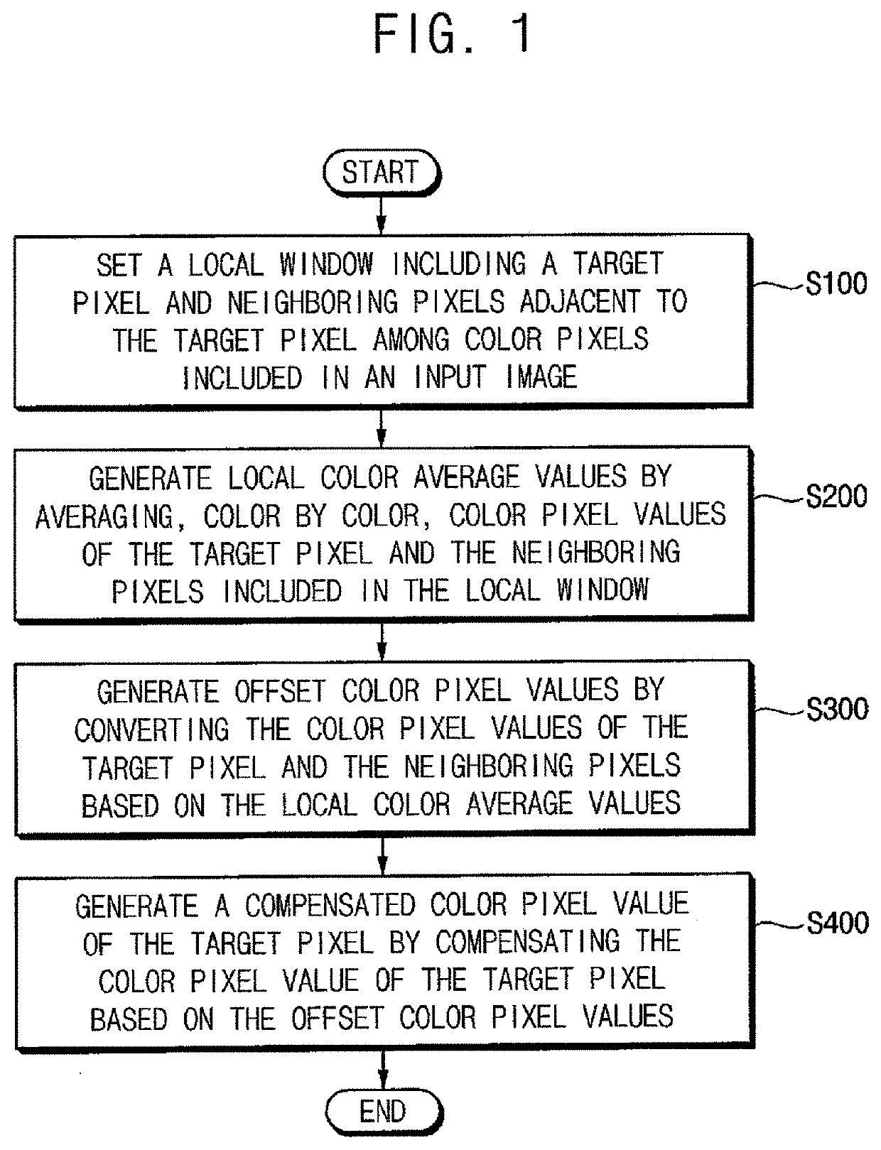
[0035]FIG. 1 is a flowchart illustrating a denoising (e.g., reducing noise) method according to example embodiments.

[0036]Referring to FIG. 1, a local window including a target pixel and neighboring pixels adjacent to the target pixel may be set among color pixels included in an input image (S100). The input image may correspond to a color filter array of an image sensor that generates the input image. The color filter array may be a mosaic of tiny color filers placed over the image sensor to capture color information. Each filter within the mosaic may cover one pixel (i.e., “sensor element” or “pixel sensor”) in the image sensor. Each filter in combination with the pixel that the filter covers may generate a color ...


PUM


Abstract

A method of reducing noise in an input image by setting, as a local window among color pixels included in the input image, a target pixel and neighboring pixels adjacent to the target pixel, determining color pixel values for the target pixel and each of the neighboring pixels included in the local window, generating local color average values are generated by averaging, color by color, the color pixel values, generating offset color pixel values by converting the color pixel values of the target pixel and the neighboring pixels based on the local color average values, and generating a compensated color pixel value of the target pixel by adjusting the color pixel value of the target pixel based on the offset color pixel values.

Description

CROSS-REFERENCE TO RELATED APPLICATION[0001]This U.S. non-provisional application claims priority under 35 USC § 119 to Korean Patent Application No. 10-2021-0055425, filed on Apr. 29, 2021, in the Korean Intellectual Property Office (KIPO), the disclosure of which is incorporated by reference herein in its entirety.BACKGROUND1. Technical Field[0002]Example embodiments relate generally to image processing, and more particularly to a denoising method and a denoising device for reducing noise in an input image corresponding to a color filter array of an image sensor.2. Discussion of the Related Art[0003]Complementary metal oxide semiconductor (CMOS) image sensors are solid-state sensing devices that use complementary metal oxide semiconductors. CMOS image sensors have lower manufacturing costs and lower power consumption compared with charge-coupled device (CCD) image sensors. Thus CMOS image sensors are used for various electronic appliances including portable devices such as, for ex...

Claims


Application Information

Patent Timeline
IPC IPC(8): H04N9/79H04N9/04G06T5/00G06T3/40
CPCH04N9/7908H04N9/04515H04N9/04557G06T5/002G06T5/004G06T3/4015G06T2207/10024G06T2207/20024H04N25/13H04N25/133H04N23/84H04N25/135H04N25/134H04N23/12G06T5/20G06T5/70H04N25/671G06T7/13H04N25/11G06T5/00H04N23/843G06T5/75
Inventor KIM, PILSUCHOI, SEUNGWONCHOI, JONGSEONG
Owner SAMSUNG ELECTRONICS CO LTD
Learn More