Camera based six degree-of-freedom target measuring and target tracking device with rotatable mirror

Inactive Publication Date: 2007-10-25
FARO TECH INC
View PDF6 Cites 106 Cited by
  • Summary
  • Abstract
  • Description
  • Claims
  • Application Information

AI Technical Summary

Benefits of technology

[0015]For example, one specific method comprises a camera based target coordinate measuring method for use in measuring the position of objects without requiring use a laser range finder for measuring distance comprising operating a mirror rotatable about a first axis and a second axis; operating a camera located to receive light emitted by the light sources that is reflected off the mirror; placing a target to view with the mirror and having at least three or more light sources wherein the light sources are located on the target at known three-dimensional coordinates relative to each other and wherein at least one of the light sources is located at a different distance from the mirror than the midpoint of a line segment connecting two of the other light sources, and wherein the target is structured to be placed on an object to be measured or to be placed on a device to measure the object; measuring angles of rotation of the mirror about the first and second axes with two angular measuring devices; rotating the mirror about the first and second axes with at least one motor; recording the images of the light sources on a photosensitive pixel array located in the camera; and determining in a processor up to three positional degrees of freedom and up to three rotational degrees of freedom of the target.

Problems solved by technology

This high level of measurement accuracy is usually only associated with more expensive laser based devices.

Method used


Image

  • Camera based six degree-of-freedom target measuring and target tracking device with rotatable mirror
  • Camera based six degree-of-freedom target measuring and target tracking device with rotatable mirror
  • Camera based six degree-of-freedom target measuring and target tracking device with rotatable mirror

Examples


first embodiment

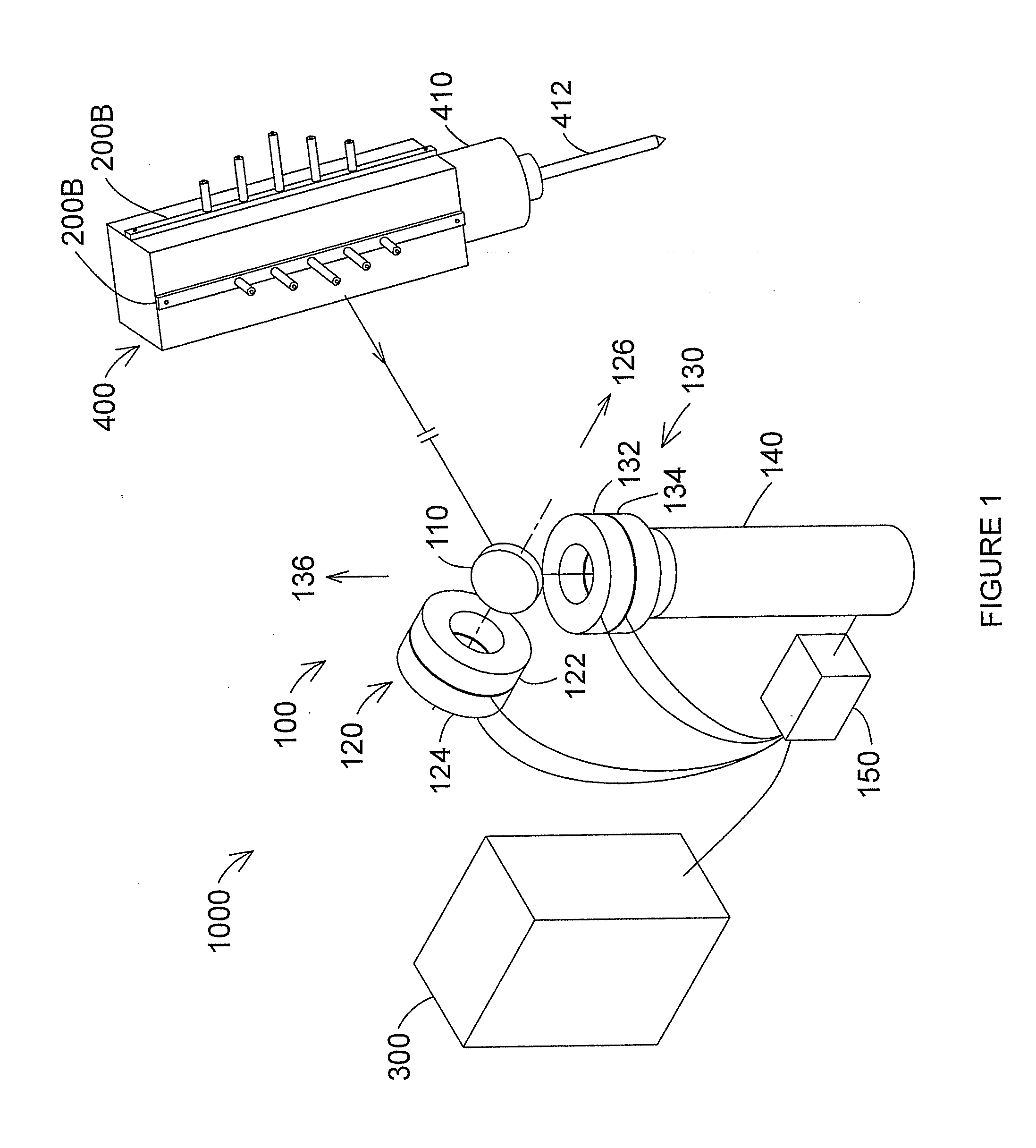
[0037]With reference to FIG. 2, target 200 comprises at least three points of light at fixed positions relative to one another. In general, by using more than 3 points, it is possible to maintain high radial accuracy over an extended range. For example, target 200A, which is target 200, comprises points of light 210, 211, and 212, pedestal 220, and base 230. Points of light are preferably LEDs but may be other types of active light sources or may also be passive reflectors. An example of a passively reflector is a photogrammetric spot that is illuminated by flashing lights located in the vicinity of 6-DOF tracker 1000.

second embodiment

[0038]Target 200B, which is target 200, comprises seven points of light 240-246, five pedestals 250-254, and base 260. In operation, additional points of light on target 200B are turned on as target 200B moves away from 6-DOF tracker 1000 with camera 140. Thus, when the target 200B is located close to 6-DOF tracker 1000, points of light 242, 243, and 244 illuminate. Farther away, points of light 241 and 245 also illuminate. Still farther away, additional points of light 240 and 246 also illuminate Alternatively, all seven points of light may be illuminated at all times, with more points of light coming into view as distance is increased.

[0039]Ordinarily base 230 or 260 is attached to some other object whose six degrees of freedom are to be measured. Pedestals such as 220 and 250-254 provide a geometry that is favorable for high accuracy measurement of radial distance to the object. A light source is mounted onto a pedestal so that its axis of emission is approximately in line with t...


PUM


Abstract

An embodiment may comprise a camera based target coordinate measuring system or apparatus for use in measuring the position of objects in manner that preserves a high level of accuracy. This high level of measurement accuracy is usually only associated with more expensive laser based devices. Many different arrangements are possible. Other embodiments may comprise related methods of using a camera based target coordinate measuring method for use in measuring the position of objects. Many variations on the methods are possible. For example, a camera based coordinate measuring system for use in measuring the position of a target relative to at least one frame of reference without requiring use of a laser range finder for measuring distance may comprise at least three or more light sources located on a target wherein the light sources are located on the target at known three-dimensional coordinates relative to each other; at least one rotatable mirror rotatable on about a first axis and a second axis; a camera located to receive light emitted by the light sources that is reflected off the minor; two angular measuring devices to measure the angles of rotation of the mirror about the first and second axes; and a processor for determining up to three positional degrees of freedom and up to three rotational degrees of freedom of the target.

Description

CROSS REFERENCE[0001]This application claims priority to U.S. provisional application, 60 / 793,811, filed Apr. 21, 2006, the entire contents of which are incorporated herein by reference.BACKGROUND[0002]The present disclosure relates to a coordinate measuring device. One set of coordinate measurement devices belongs to a class of instruments that measure the three-dimensional coordinates of a point by sending a laser beam to the point. The laser beam may impinge directly on the point or may impinge on a retroreflector target that is in contact with the point. In either case, the instrument determines the coordinates of the point by measuring the distance and the two angles to the target. The distance is measured with a distance-measuring device such as an absolute distance meter or an interferometer. The angles are measured with an angle-measuring device such as an angular encoder. A gimbaled beam-steering mechanism within the instrument directs the laser beam to the point of interes...

Claims


Application Information

Patent Timeline
Patent Type & Authority Applications(United States)
IPC IPC(8): G01B11/26G01C1/00
CPCG01S5/163G01B11/002
Inventor BRIDGES, ROBERT E.
Owner FARO TECH INC
Why Eureka
Try Eureka