
Dynamic crack length measurement method for machine vision fatigue crack propagation test

A technology of fatigue crack growth and crack length, which is applied in the direction of measuring device, using applied repetitive force/pulsation force to test material strength and strength characteristics, etc. It can solve the problems of cumbersome process, poor anti-interference, and inability to accurately measure crack length.

Active Publication Date: 2012-09-26
平邑经济开发区投资发展有限公司
View PDF4 Cites 73 Cited by
  • Summary
  • Abstract
  • Description
  • Claims
  • Application Information

AI Technical Summary

Problems solved by technology

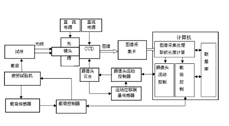
[0009] In order to overcome the cumbersome process of the existing dynamic measurement method of crack length in fatigue crack growth test, heavy labor, low precision, poor anti-interference, the process of crack growth cannot be observed and recorded intuitively and accurately, and the calculated crack length stipulated by international standards cannot be accurately measured The present invention provides a fatigue crack detection method based on machine vision technology that simplifies the process, reduces labor load, has high precision, good anti-interference performance, can observe and record the crack growth process intuitively and accurately, and accurately calculate the calculated crack length stipulated by international standards. Dynamic measurement method of crack length in growth test

Method used


Image

  • Dynamic crack length measurement method for machine vision fatigue crack propagation test
  • Dynamic crack length measurement method for machine vision fatigue crack propagation test
  • Dynamic crack length measurement method for machine vision fatigue crack propagation test

Examples


Embodiment approach

[0114] Step 1: This method combines Figure 4 The C(T) compact tensile fatigue test fixture shown in the figure is implemented by installing and positioning device, which consists of specimen 3, fixture 4, positioning sleeve 5, positioning screw 1, compression washer, lock nut 2, fixture installation and positioning method Composed of blue 6, the fixture assembly has two upper and lower fixtures, which are symmetrical with respect to the center line of the test piece. The test piece is installed in the middle of the upper and lower fixtures, through two equal-length positioning sleeves 5 and positioning screw 1, compression washers, and lock nuts 2 Install and position, make the force line HI of the test piece coincide with the center line of the fixture to ensure that the test load generated by the testing machine acts on the test piece along the force line of the test piece through the fixture superior. In the figure, 8 is the extended fatigue crack, and 7 is the prefabrica...


PUM


Abstract

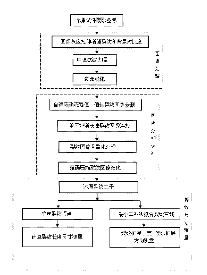
The invention provides a dynamic crack length measurement method for a fatigue crack propagation test based on the machine vision technology. The method comprises the following steps: 1, performing machine vision crack measurement system calibration; 2, performing fatigue test, wherein a test piece with precracks begins to generate fatigue cracks along the direction of the precracks, and the fatigue cracks extend; 3, collecting crack images, wherein a mode of collecting single-face images of the test piece and a mode of collecting two-side images of the test piece are used in the fatigue crack propagation test; 4, reinforcing the collected images; 5, identifying the position of the trunk of cracks, as well as peaks and identifying directions of cracks by using the method of image analysis and crack identification; and 6, calculating the actual crack identifying length and crack length. The method has the advantages of simplifying the process and reducing work load; and by the method, the crack identifying process can be visually and accurately observed and recorded, the calculated crack length specified by the international standard can be measured accurately. The method also has the advantages of high measurement accuracy and good system anti-jamming performance.

Description

technical field [0001] The invention relates to a method for measuring the crack length of a fatigue crack extension test. Background technique [0002] The metal fatigue crack growth test is a test method to study the fatigue fracture characteristics of metal materials by measuring the length of fatigue cracks generated by the specimen under the action of a set alternating load in real time. At present, the main form of fatigue crack growth test is the international The C(T) compact tensile test and the three-point bending crack growth test with pre-cracks specified in the standard, in this case, the fatigue cracks basically extend linearly along the direction of the pre-cracks under the action of the set alternating load, Other non-standard fatigue crack growth tests are basically in this form, but the shape and size of the test piece are changed. [0003] The initiation and propagation of fatigue cracks is a complex and slow nonlinear evolution process. The traditional m...

Claims


Application Information

Patent Timeline
Patent Type & Authority Applications(China)
IPC IPC(8): G01B11/02G01N3/32G01N3/06
Inventor 高红俐齐子诚吴丽华王建淼邵新阳
Owner 平邑经济开发区投资发展有限公司
Learn More