Optical Low Pass Filter and Image -Capturing Device

a filter and low-pass technology, applied in the field of optical low-pass filter and image capture device, can solve the problems of deterioration of photographic image phenomena, and achieve the effect of simple and easy manner

Inactive Publication Date: 2007-10-25
NIKON CORP
View PDF5 Cites 10 Cited by
  • Summary
  • Abstract
  • Description
  • Claims
  • Application Information

AI Technical Summary

Benefits of technology

[0020] Since, according to the present invention, by generating a refractive index distribution that changes cyclically within the plane of the light transmitting member, the incident light beam is separated by diffraction, accordingly it is possible to change the separation characteristics of the optical low pass filter in a simple and easy manner by, for example, varying the refractive index distribution by varying the electrical power supplied to the piezoelectric element in a range from zero to P.

Problems solved by technology

At this time, if a high frequency component which is at the same frequency level or higher than the sampling frequency of the image sensor is included in the image of the object to be photographed, then the phenomenon of deterioration of the photographic image may occur, which is undesirable.

Method used


Image

  • Optical Low Pass Filter and Image -Capturing Device
  • Optical Low Pass Filter and Image -Capturing Device
  • Optical Low Pass Filter and Image -Capturing Device

Examples


Embodiment Construction

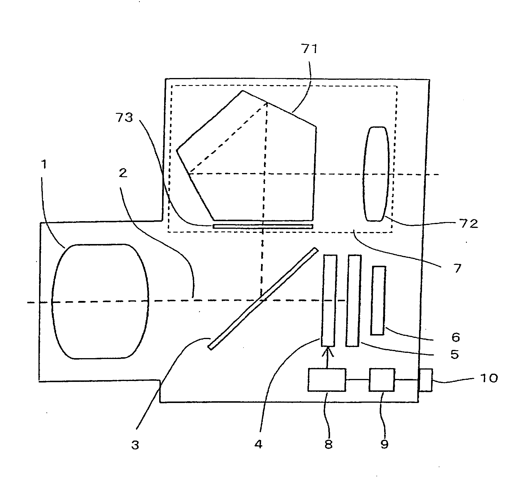
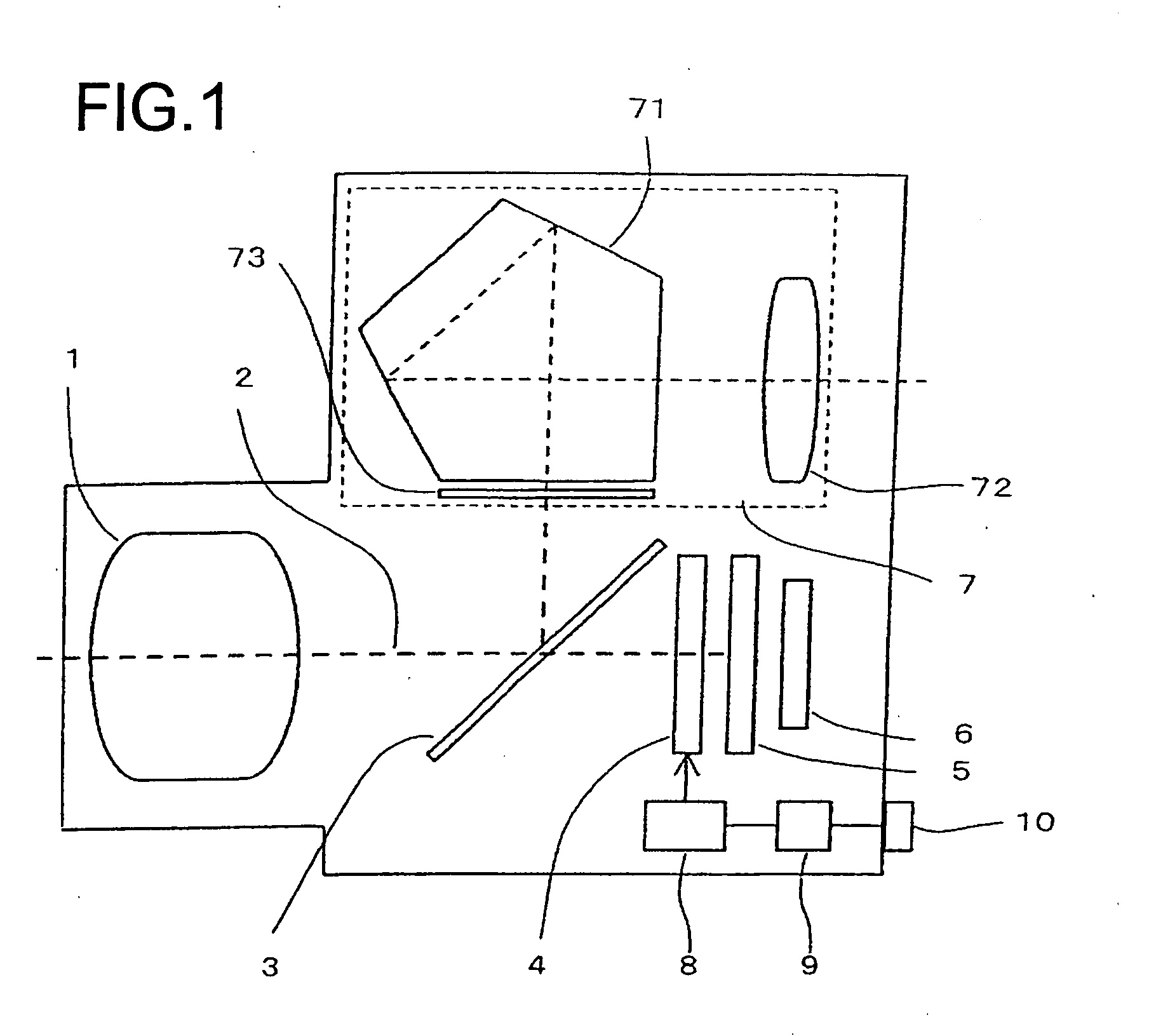
[0036] In the following, embodiments of the present invention will be explained with reference to the drawings. FIG. 1 is a figure showing an embodiment of the image-capturing device of the present invention, and shows the general structure of a single lens reflex type digital still camera. In FIG. 1, the reference symbol 1 denotes a photographic optical system, while 3 is a quick return mirror, 4 is an optical low pass filter, 5 is a focal plane shutter, 6 is an image sensor, 7 is a viewfinder optical system, 8 and is a drive circuit for the optical low pass filter 4. The drive circuit 8 is connected to a control unit 9. The reference symbol 10 denotes an actuation unit which comprises an actuation button or an actuation dial or the like: it is possible for the user to issue various types of actuation command to the camera by actuating this actuation unit 10. Furthermore, although this is not shown in the figure, the camera comprises a display section such as an LCD monitor or the ...


PUM


Abstract

An optical low pass filter includes: a light transmitting member (41); and a refractive index distribution generation means (42) that generates a refractive index distribution cyclically changing within the plane of the light transmitting member (41). The refractive index distribution generation means includes a piezoelectric element, for example, and generates the refractive index distribution by generating the compressional wave in the light transmitting member (41) with a high frequency voltage being applied to the piezoelectric element.

Description

TECHNICAL FIELD [0001] The present invention relates to an optical low pass filter which performs light beam branching, and to an image-capturing device which utilizes this optical low pass filter. BACKGROUND ART [0002] In an image-capturing device such as a video camera or a digital camera or the like which employs an image sensor, an image which is imaged by a lens is converted into an electrical signal by the image sensor. At this time, if a high frequency component which is at the same frequency level or higher than the sampling frequency of the image sensor is included in the image of the object to be photographed, then the phenomenon of deterioration of the photographic image may occur, which is undesirable. Due to this, an optical low pass filter is used with this type of image-capturing device, with the objective of attenuating high frequencies in the image formed of the object to be photographed. [0003] An optical low pass filter is a device which, by separating a beam of l...

Claims


Application Information

Patent Timeline
Patent Type & Authority Applications(United States)
IPC IPC(8): G02B5/22
CPCG02B27/46H04N5/2254G03B11/00
Inventor SHIOZAWA, MASAKINOMURA, TATSUSHI
Owner NIKON CORP
Why Eureka
Try Eureka