

Protective structure for electrostatic discharge
- Summary
- Abstract
- Description
- Claims
- Application Information
AI Technical Summary
Benefits of technology
Problems solved by technology
Method used
Image

Examples
first embodiment
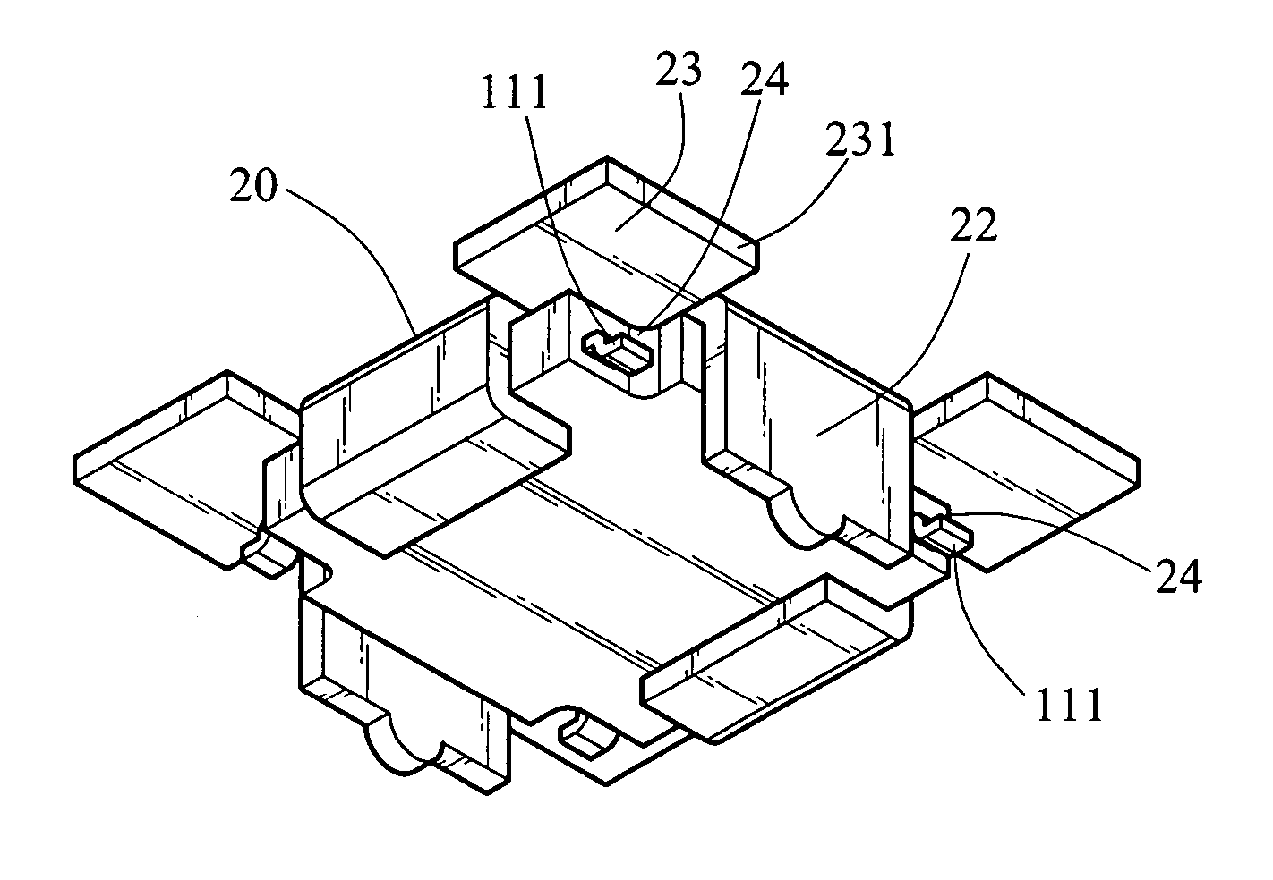
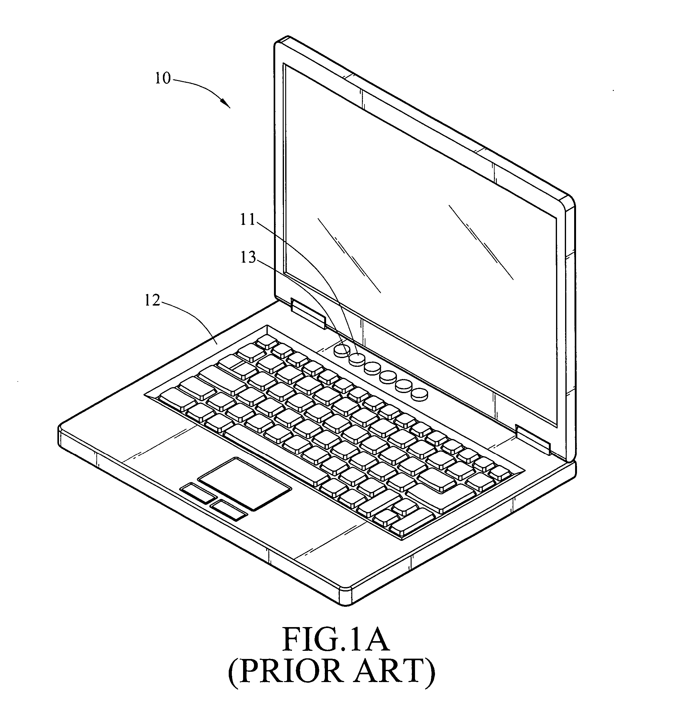
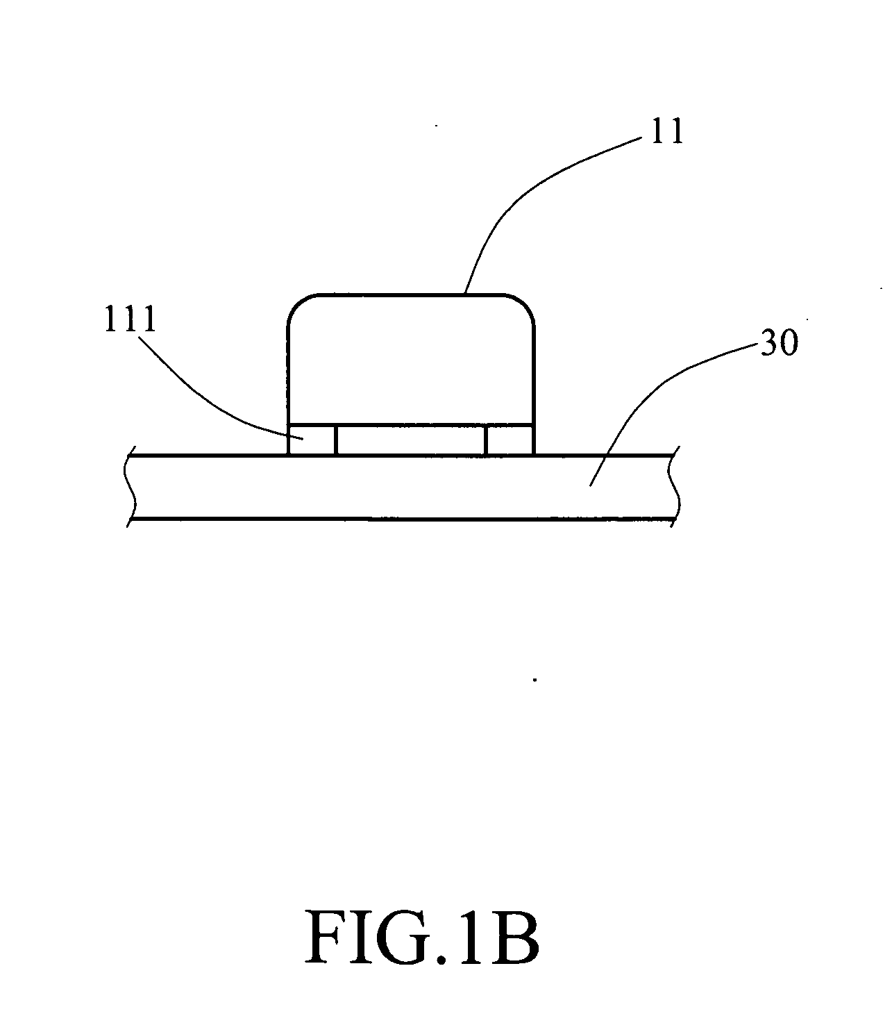
[0024] the invention is shown as FIG. 1A, FIG. 1B, and FIG. 4. A notebook computer 10 in the embodiment shown in the drawings has at least one access key 11 comprising a signal output / input portion 111. A masking piece 20 made of conductive material may be disposed at the position of the access key 11, for wrapping the access key 11, which protects the access key 11 of the notebook computer 10 from being interfered and damaged by electrostatic discharge, such that the notebook computer 10 will not be rendered inoperative. The masking piece 20 comprises a ground portion 22 and a protrusion 23, wherein the ground portion 22 is located approximately at the bottom of the access key 11, and the protrusion 23 is disposed corresponding to the position of the signal output / input portion 111 and having a level edge 231. A hole 210 in which the access key 11 is located to be wrapped is opened on the masking piece 20, while the protrusion 23 is disposed extendedly along the edge of the masking...
second embodiment
[0027] the invention is shown in FIG. 1A, FIG. 5, and FIG. 6. A masking piece 20b is shown in the drawings, which comprises a ground portion 22b and a protrusion 23b, wherein the ground portion 22b is located approximately at the bottom of the access key 11, and the protrusion 23b is disposed corresponding to the position of the signal output / input portion 111 and having a plurality of successive zig-zag cuts 231b. A hole 210b is opened on the masking piece 20b, wherein the access key 11 is located in and wrapped by the hole 210b. The protrusion 23b is disposed extendedly along the edge of the masking piece 20b. A difference in height exists between the bottoms of the protrusion 23b and the masking piece 20b, therefore, a masking area 24b located above the signal output / input portion 111 is formed. The top surfaces of the masking piece 20b and the protrusion 23b are coplanar, and the ground portion 22b is disposed extendedly along the edge of the masking piece 20b corresponding to t...
PUM
 Abstract
Description
Claims
Application Information