Spine fixation method and apparatus

a spine and fixation method technology, applied in the field of spine fixation methods and apparatuses, can solve the problems of adding another level of complexity to the operation, increasing the operative time, and adding considerable time to the operation, so as to reduce the operating time and the risk of spinal injury during surgery, and improve the stability. the effect of stability

Active Publication Date: 2007-10-25
KIC VENTURES LLC
View PDF29 Cites 251 Cited by
  • Summary
  • Abstract
  • Description
  • Claims
  • Application Information

AI Technical Summary

Benefits of technology

[0010]Among the advantages of this invention may be one or more of the following. The improved spinal fixation system allows segmented fixation of the spine in all three directions and multi-axial anchoring of the fixation elements. The use of multip...

Problems solved by technology

This may add considerable time to an operation.
However, in most cases this adds another level of complexity to the operation and often further increases the operative time.
This increase in operative time and the complexity of the connectors put substantial stress on the surgeon and the support...

Method used


Image

  • Spine fixation method and apparatus
  • Spine fixation method and apparatus
  • Spine fixation method and apparatus

Examples


Embodiment Construction

[0026]The invention provides a spine fixation apparatus with a multi-axial screw assembly that utilizes a multi-axial screw housing and adjustable, mounting elements for receiving stabilization elements with various geometries

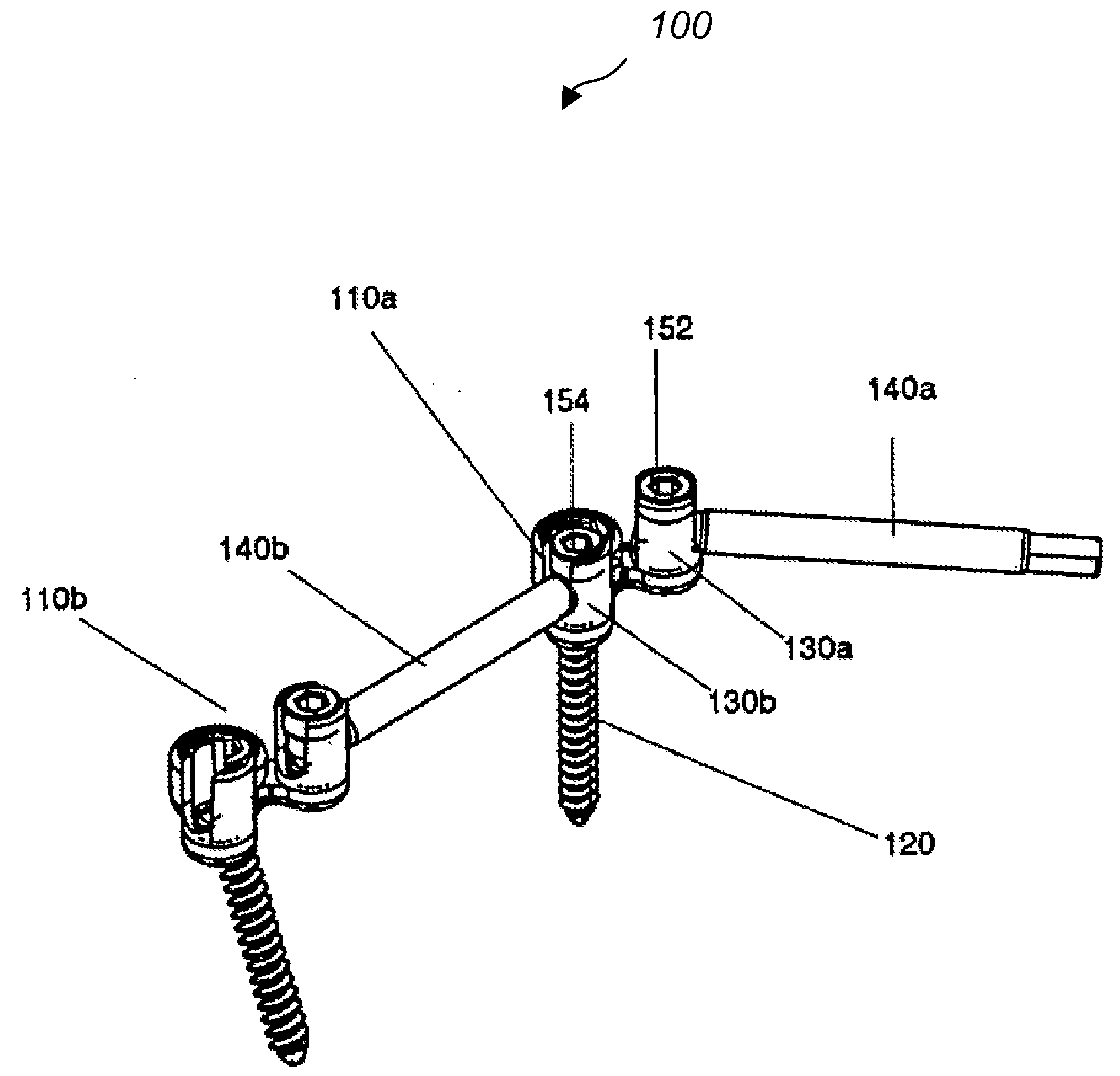
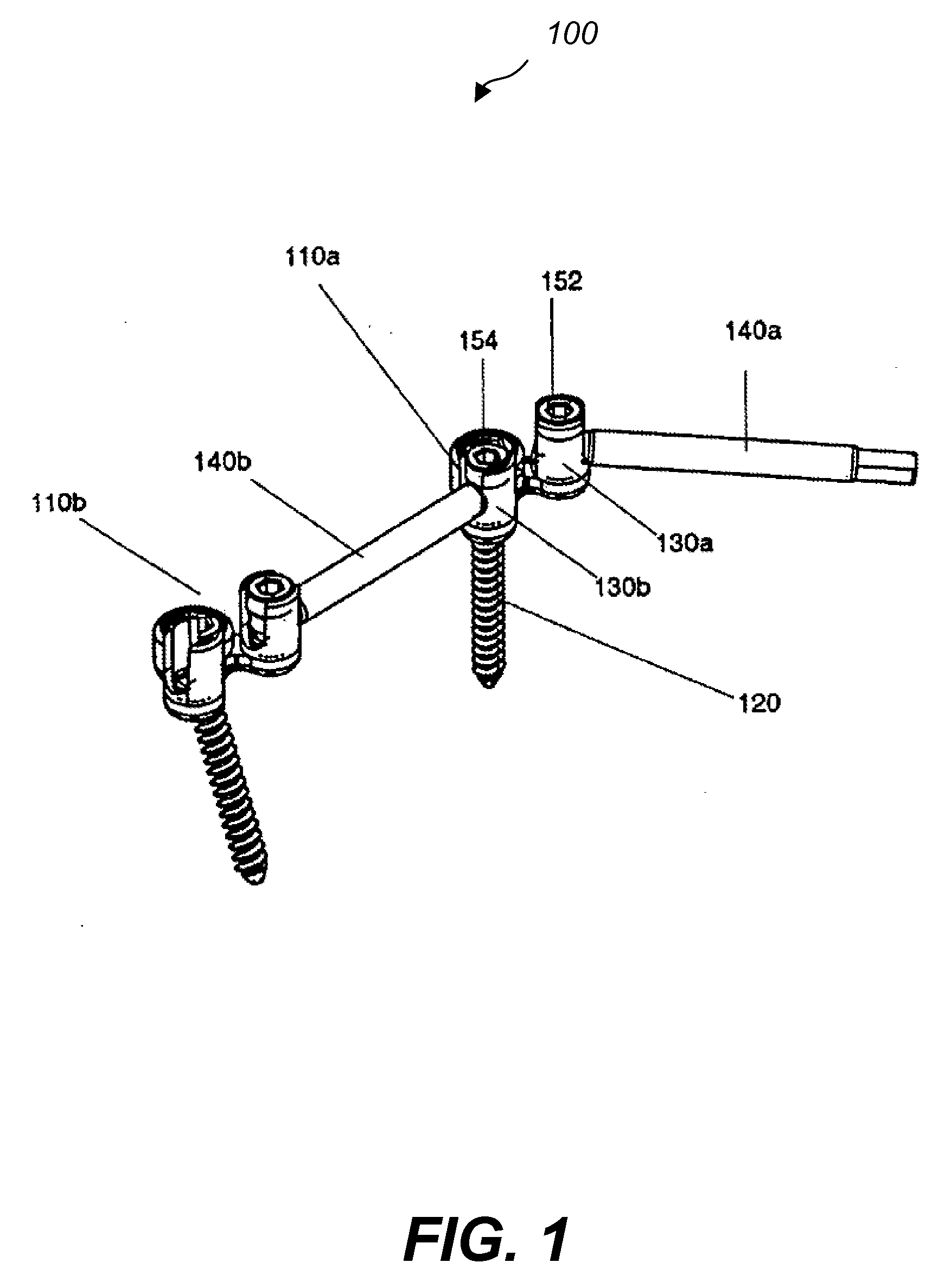
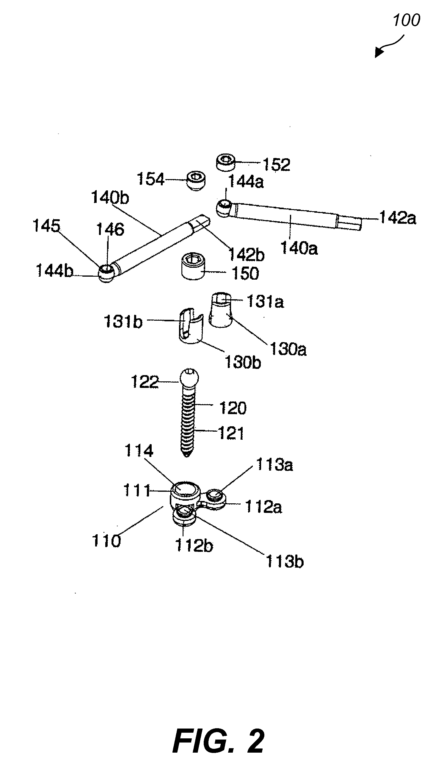
[0027]Referring to FIG. 1, a spine fixation assembly 100 includes mounting assemblies 110a, 110b and stabilization rods 140a, 140b. Stabilization rod 140b is placed and secured in the mounting assemblies 110a, 110b and thereby connects them. Referring to FIG. 2, the mounting assembly 110 includes a multiaxial screw housing 111, two mounting plates 112a, 112b extending from the housing 111 and two mounting elements 130a, 130b. The screw housing 111 includes a through opening 114 for receiving a bone screw 120. Opening 114 extends from the top surface of the screw housing 111 to the bottom surface and has a diameter at the top larger than the diameter at the bottom. The bone screw 120 has a body 121 with outer threads and a spherical head 122. The body 121 is ins...


PUM


Abstract

A spine fixation assembly connecting a first vertebra to a second vertebra includes first and second mounting assemblies and a first spinal stabilization component. The first mounting assembly is configured to be attached to a first location of the first vertebra and includes a first bone anchor housing and first and second spinal stabilization component housings extending from the first bone anchor housing. The second mounting assembly is configured to be attached to a first location of the second vertebra and includes a second bone anchor housing and third and fourth spinal stabilization component housings extending from the second housing. The first spinal stabilization component includes an elongated body having a first end and a second end and is configured to connect the first mounting assembly to the second mounting assembly. The first spinal stabilization component housing is adapted to receive and connect to the first end of the spinal stabilization component and the third spinal stabilization component housing is adapted to receive and connect to the second end of the spinal stabilization component.

Description

CROSS REFERENCE TO RELATED CO-PENDING APPLICATIONS[0001]This application claims the benefit of U.S. provisional application Ser. No. 60 / 794,355 filed Apr. 24, 2006 and entitled “IMPROVED SPINE FIXATION METHOD AND APPARATUS, the contents of which are expressly incorporated herein by reference.FIELD OF THE INVENTION[0002]The present invention relates to an improved spine fixation method and apparatus, and more particularly to a spine fixation method and apparatus that utilizes adjustable, multi-axial mounting assemblies for receiving segments of stabilization elements with various geometries.BACKGROUND OF THE INVENTION[0003]Several prior art spine fixation assemblies utilize rods and / or plates as connecting and stabilization elements between vertebral elements. The rods are secured to vertebral bones left and right the spinal midline via screws. The screws in some of the prior art assemblies are capable of pivoting around a fixed axis of the stabilization rods to achieve variable angu...

Claims


Application Information

Patent Timeline
IPC IPC(8): A61B17/58
CPCA61B17/7001A61B17/7005A61B17/705A61B17/7032A61B17/7035A61B17/7007
Inventor CHIN, KINGSLEY R.IBARRA, MATTHEW
Owner KIC VENTURES LLC
Why Eureka
Try Eureka