Tower adapter, method of producing a tower foundation and tower foundation

a technology of adapter and tower, which is applied in the direction of foundation engineering, mechanical equipment, building repairs, etc., can solve the problems of no further work on the particular tower construction site, no grout cure time, and even longer time-consuming

Active Publication Date: 2007-11-01
GENERAL ELECTRIC CO
View PDF30 Cites 68 Cited by
  • Summary
  • Abstract
  • Description
  • Claims
  • Application Information

AI Technical Summary

Benefits of technology

[0008] According to a first aspect of the invention, a means for connecting a foundation to a tower is provided. The connecting means includes a hollow portion having a closed cross-section, and a flange portion extending perpendicularly to the hollow portion at a first end thereof and having a plurality of first bores, wherein the ratio of the length of the hollow portion and a maximum diameter of the connecting means is smaller than or equal to 1.

Problems solved by technology

However, the bottom part of the tower has to be placed on the grout joint before the grout has finally cured.
Typically, the curing of the grout takes at least 24 hours but may take even longer according to the conditions at the construction site.
During this curing time of the grout joint, no further work can be done on the particular tower construction site.
For example, the bottom section of a wind turbine tower is relatively large, typically about 10 m to 20 m long, and accordingly also relatively heavy.
However, after placing the bottom section on the grout joint the two mobile cranes are of no particular use until the grout joint has finally cured and further tower sections can be installed.
Since mobile cranes are very expensive, it is economically detrimental if they are idle for longer times. Since the construction sites of wind turbines are often remote, it is also often economically detrimental to relocate the mobile cranes for the curing time of the grout joint.

Method used


Image

  • Tower adapter, method of producing a tower foundation and tower foundation
  • Tower adapter, method of producing a tower foundation and tower foundation
  • Tower adapter, method of producing a tower foundation and tower foundation

Examples


Embodiment Construction

[0026] Reference will now be made in detail to the various embodiments of the invention, one or more examples of which are illustrated in the figures. Each example is provided by way of explanation of the invention, and is not meant as a limitation of the invention. For example, features illustrated or described as part of one embodiment can be used on or in conjunction with other embodiments to yield yet a further embodiment. It is intended that the present invention includes such modifications and variations.

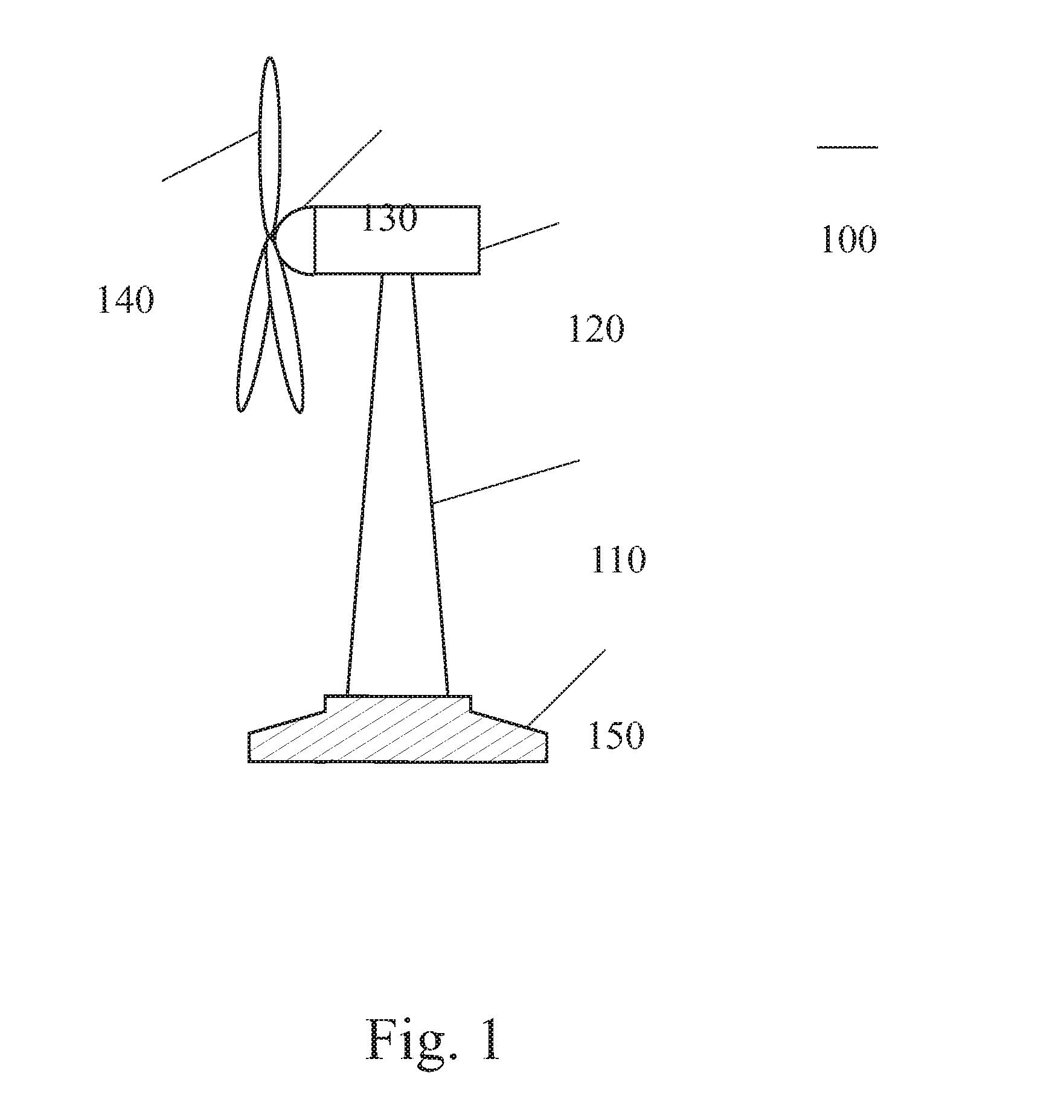
[0027]FIG. 1 shows a wind turbine to which the embodiments of the present invention can be advantageously applied. However, it should be understood that the present invention is not limited or restricted to wind turbines but can also be applied to tower structures used in other technical fields. In particular, the various embodiments of the present invention may also be applied to antenna towers used in broadcasting or mobile telecommunication or to pylons used in bridge work...


PUM


Abstract

A tower adapter is provided, the tower adapter includes a cylindrical portion extending in a longitudinal direction of the adapter, and a first lateral portion extending perpendicularly to the cylindrical portion at a first end thereof and having a plurality of first through-holes. The ratio of a maximum longitudinal extension and a maximum lateral extension of the adapter is smaller than or equal to 1.

Description

BACKGROUND OF THE INVENTION [0001] This invention relates generally to a tower adapter, a method of producing a tower foundation and a tower foundation. In particular but not limited thereto, the present invention relates to a tower adapter for a wind turbine tower, a method for producing a foundation of a wind turbine tower, and a foundation of a wind turbine tower. [0002] Several technical installations require a tower or a mast to which the installation is mounted. Non-limiting examples of such installations are wind turbines, antenna towers used in broadcasting or mobile telecommunication, pylons used in bridge work, or power poles. Typically, the tower is made of steel and must be connected to a foundation made of reinforced concrete. In these cases, the typical technical solution is to provide a flange with through-holes at the bottom of the tower. Anchor bolts are inserted into the through-holes and are fastened with nuts. Typically, the anchor bolts are connected to an ancho...

Claims


Application Information

Patent Timeline
Patent Type & Authority Applications(United States)
IPC IPC(8): E04B1/00
CPCE02D27/42Y02E10/728F03D11/045E04H12/085F03D13/22E02D27/425Y02E10/72
Inventor SCHIFFER, JORISLELAND, KENNETH
Owner GENERAL ELECTRIC CO
Why Eureka
Try Eureka