Electromagnetically Driven Valve

a technology of electric drive valve and drive valve body, which is applied in the direction of valve operating means/release devices, machines/engines, non-mechanical valves, etc., can solve the problems of increased slide resistance and failure to smooth reciprocating motion of the driven valve, and achieve smooth housing, suppressing surface abrasion, and reducing slide resistance.

Inactive Publication Date: 2007-11-01
TOYOTA JIDOSHA KK
View PDF8 Cites 0 Cited by
  • Summary
  • Abstract
  • Description
  • Claims
  • Application Information

AI Technical Summary

Benefits of technology

[0008] An electromagnetically driven valve according to the present invention includes: a driven valve having a valve shaft extending in a prescribed direction and a valve element provided at a tip end of the valve shaft and opening / closing an intake / exhaust port; an oscillating member having one end coupled to the valve shaft and the other end supported by a supporting member so as to allow free oscillation of the oscillating member and oscillating around the other end so as to cause the driven valve to carry out reciprocating motion in the prescribed direction; a buffer member provided in the valve shaft between the tip end where the valve element is provided and a position where one end is coupled; and a guide member guiding the buffer member along the prescribed direction. The buffer member contracts and expands in the prescribed direction and accommodates displacement of the valve shaft produced in a direction orthogonal to the prescribed direction as a result of reciprocating motion of the driven valve.
[0009] According to the electromagnetically driven valve structured as above, the buffer member is guided by the guide member along the prescribed direction. Accordingly, while movement of the buffer member in the direction orthogonal to the prescribed direction is restricted, displacement of the valve shaft produced in the orthogonal direction can be accommodated. At the same time, the buffer member contracts and expands in the prescribed direction, so that registration error of the valve element caused by a difference from the valve shaft in thermal expansion or part assembly error can be accommodated. Therefore, according to the present invention, smooth reciprocating motion of the driven valve can be achieved while sufficient sealing of the intake / exhaust port by means of the valve element is ensured.
[0010] Preferably, the valve shaft has a first shaft portion located on a side where one end is coupled with respect to the buffer member and a second shaft portion located on a side of the valve element with respect to the buffer member. The first shaft portion includes a first end surface abutting on a surface of the buffer member. The first end surface makes sliding movement with respect to the surface of the buffer member, so that displacement of the valve shaft produced in the direction orthogonal to the prescribed direction is accommodated. According to the electromagnetically driven valve structured as above, displacement of the valve shaft produced in the direction orthogonal to the prescribed direction can be accommodated by using a simplified structure.
[0011] Preferably, the second shaft portion includes a second end surface connected to a surface of the buffer member, and the first shaft portion is formed such that the first end surface has an area larger than that of the second end surface. According to the electromagnetically driven valve structured as above, a contact area between the first end surface and the surface of the buffer member is increased, so that slide resistance produced therebetween can be made smaller. Therefore, displacement of the valve shaft produced in the direction orthogonal to the prescribed direction can smoothly be accommodated, while suppressing abrasion of the surface of the buffer member.
[0012] As described above, according to the present invention, an electromagnetically driven valve attaining smooth reciprocating motion of the driven valve can be provided.

Problems solved by technology

Such displacement causes failure in smooth reciprocating motion of the driven valve or increase in slide resistance between the stem and a guide for guiding the stem.

Method used


Image

  • Electromagnetically Driven Valve
  • Electromagnetically Driven Valve
  • Electromagnetically Driven Valve

Examples


first embodiment

[0024] (First Embodiment)

[0025] The electromagnetically driven valve according to the present embodiment implements an engine valve (an intake valve or an exhaust valve) in an internal combustion engine such as a gasoline engine or a diesel engine. In the present embodiment, description will be given assuming that the electromagnetically driven valve implements an intake valve, however, it is noted that the electromagnetically driven valve is similarly structured also when it implements an exhaust valve.

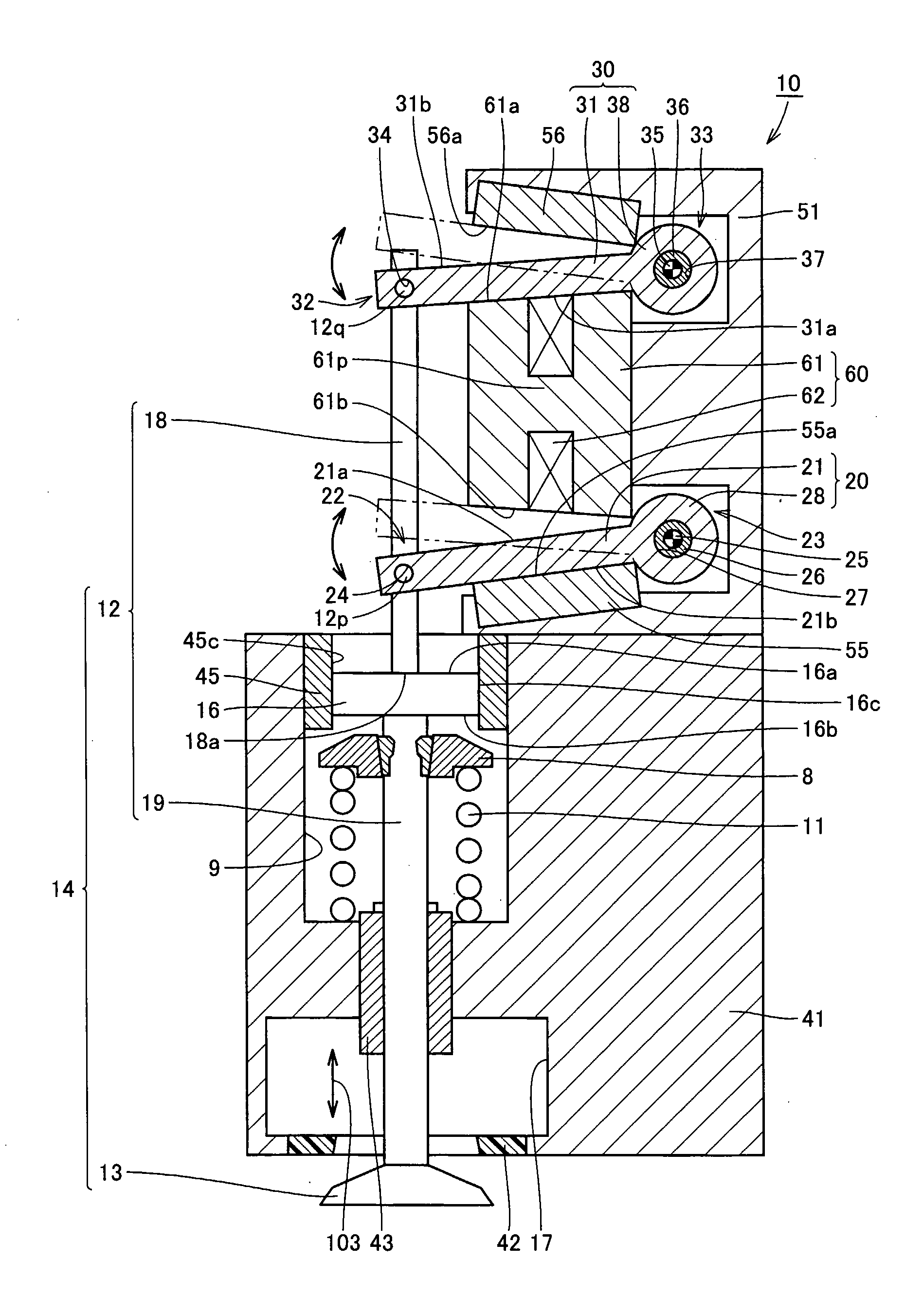
[0026] Referring to FIG. 1, an electromagnetically driven valve 10 is a rotary drive type electromagnetically driven valve. As an operation mechanism for the electromagnetically driven valve, a parallel link mechanism is applied.

[0027] Electromagnetically driven valve 10 includes a driven valve 14 having a stem 12 extending in one direction and an umbrella-shaped portion 13 formed at a tip end of stem 12, and a lower disc 20 and an upper disc 30 coupled to different positions on st...

second embodiment

[0061] (Second Embodiment)

[0062] An electromagnetically driven valve according to the present embodiment is structured in a manner basically similar to the electromagnetically driven valve in the first embodiment. Therefore, description of a redundant structure will not be repeated.

[0063]FIG. 9 is an enlarged view of a region of the electromagnetically driven valve where the lash adjuster is provided. Referring to FIG. 9, an end surface 19a is defined at a position of lower stem 19 connected to bottom surface 16b of lash adjuster 16. In the present embodiment, the tip end of upper stem 18 is formed like a collar, such that end surface 18a has an area larger than an area of end surface 19a.

[0064] According to the electromagnetically driven valve in the second embodiment of the present invention structured as above, an effect similar to that in the first embodiment can be obtained. In addition, a contact area between end surface 18a and top surface 16a is reduced, so that smoother s...

third embodiment

[0065] (Third Embodiment)

[0066] An electromagnetically driven valve according to the present embodiment is structured in a manner basically similar to the electromagnetically driven valve in the first embodiment. Therefore, description of a redundant structure will not be repeated.

[0067]FIG. 10 is an enlarged view of a region of the electromagnetically driven valve where the lash adjuster is provided. Referring to FIG. 10, lash adjuster 16 is constituted of an upper lid 81 having top surface 16a, a lower lid 83 arranged with a prescribed distance from upper lid 81 and having bottom surface 16b, and a viscous member 82 filling a gap between upper lid 81 and lower lid 83, such as grease and oil. In the present embodiment, lower retainer 8 in FIG. 1 is not provided in lower stem 19. Lower spring 11 is housed in hollow portion 9 between the bottom surface of hollow portion 9 and lower lid 83.

[0068] In the electromagnetically driven valve according to third embodiment of the present in...


PUM


Abstract

An electromagnetically driven valve includes a driven valve having a stem extending in a prescribed direction and an umbrella-shaped portion provided at a tip end of the stem and opening/closing an intake/exhaust port, a lower disc and an upper disc having one ends coupled to the stem and the other ends supported by a disc support base so as to allow free oscillation of the disc respectively and oscillating around the other ends so as to cause the driven valve to carry out reciprocating motion in the prescribed direction, a lash adjuster provided in the stem, and a guide ring guiding the lash adjuster along the prescribed direction. The lash adjuster contracts and expands in the prescribed direction and accommodates displacement of the stem produced in a direction orthogonal to the prescribed direction as a result of reciprocating motion of the driven valve. With such a structure, the driven valve carries out smooth reciprocating motion.

Description

TECHNICAL FIELD [0001] The present invention generally relates to an electromagnetically driven valve, and more particularly to an electromagnetically driven valve of a rotary drive type used in an internal combustion engine and driven by electromagnetic force and elastic force. BACKGROUND ART [0002] With regard to a conventional electromagnetically driven valve, for example, Japanese Patent Laying-Open No. 11-30113 discloses an electromagnetically driven apparatus aiming at prevention of generation of sound caused by friction or impact at the time of opening / closing of an intake / exhaust valve as well as attaining improvement in its characteristic of being mounted on an engine. The electromagnetically driven apparatus disclosed in this publication includes an armature accommodated in a casing in a vertically movable manner, a valve-closing electromagnet and a valve-opening electromagnet fixed to positions above and below the armature respectively, and a valve-opening side spring mov...

Claims


Application Information

Patent Timeline
Patent Type & Authority Applications(United States)
IPC IPC(8): F01L9/04F01L9/20F01L9/21
CPCF01L1/24F01L2109/00F01L2009/0425F01L9/04F01L2309/00F01L2009/2125F01L9/20
Inventor SUGIE, YUTAKAASANO, MASAHIKO
Owner TOYOTA JIDOSHA KK
Why Eureka
Try Eureka