Dynamic element matching method and device

Active Publication Date: 2007-11-01
TEXAS INSTR INC
View PDF4 Cites 1 Cited by
  • Summary
  • Abstract
  • Description
  • Claims
  • Application Information

AI Technical Summary

Benefits of technology

[0009] In another embodiment of the present invention, said second time rate can be lower than said first time rate. A

Problems solved by technology

That is, as the over-sampling ratio is increased, the quantization noise (the source of the out-of-band noise) decreases, and the noise-shaped bandwidth increases.
However, if the operating frequency is too high, distortion

Method used


Image

  • Dynamic element matching method and device
  • Dynamic element matching method and device
  • Dynamic element matching method and device

Examples


Example

[0029] According to said first embodiment of the present invention, the DEM processing rate can be set differently from the processing rate for input in receiving the object of the DEM processing. Consequently, in said first embodiment of the present invention, by using a DEM processing rate lower than that for the input of the DEM processing object, it is possible to reduce the number of analog / digital switching times performed as a function of the weight generator. As the number of switching times is reduced, the distortion is reduced and the distortion performance (THD+N) is improved.

[0030] In the following, an explanation will be given in more detail regarding the embodiment of the present invention with reference to the figures.

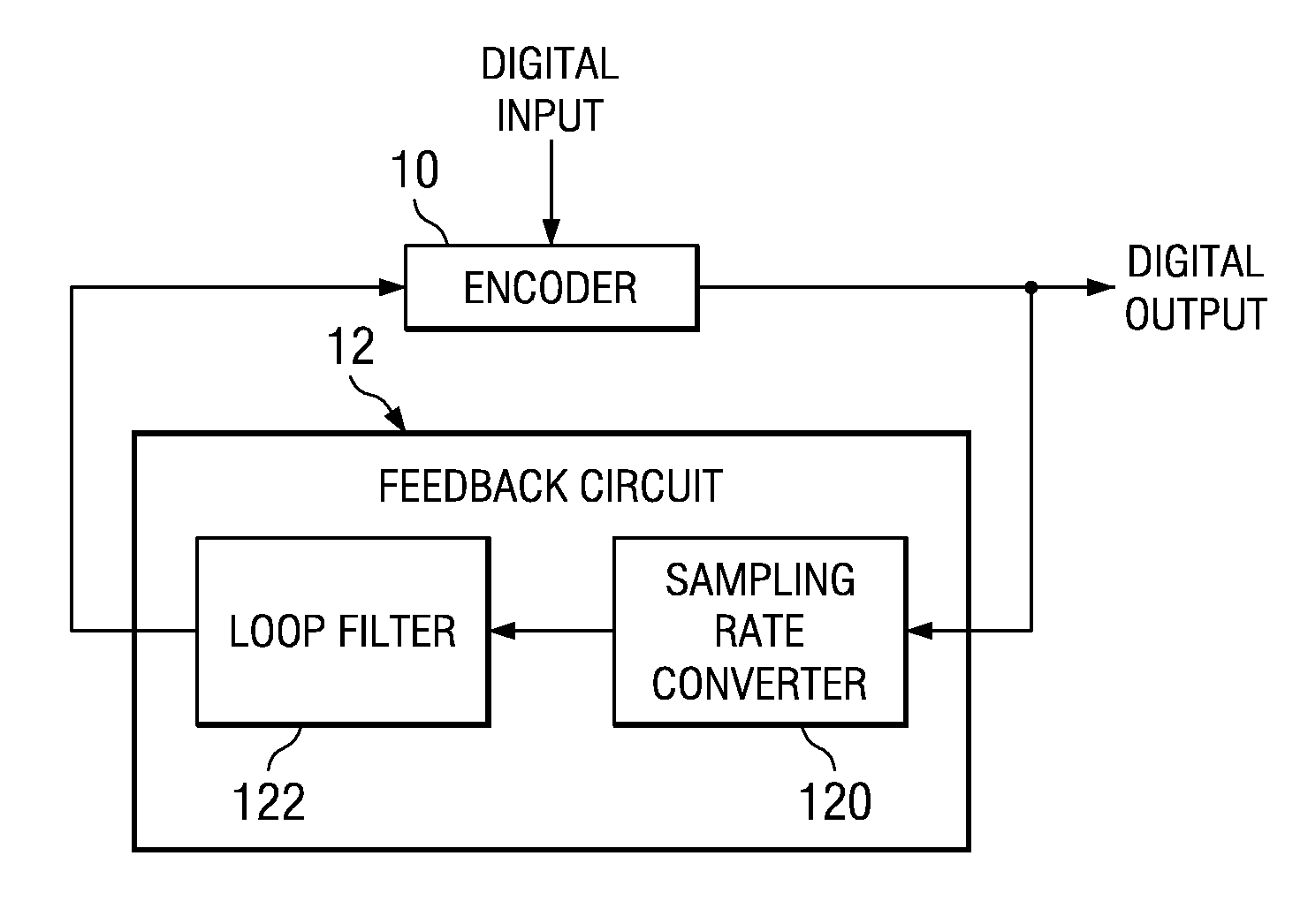
[0031] First of all, FIG. 1 shows DEM (dynamic element matching) circuit 1 as Embodiment 1 of the present invention. As shown in the figure, this DEM circuit 1 is composed of encoder 10 and feedback circuit 12. Said encoder 10 has two inputs and one ou...


PUM


Abstract

The invention provides an improved dynamic element matching (DEM) device. The DEM device performs dynamic element matching processing at a second timing rate different from the first timing rate for the digital input. As an embodiment, the DEM device is composed of encoder 10 and feedback circuit 12. Said encoder 10 has two inputs and one output. Of the two inputs, one receives the digital input as the object for the DEM processing, and the other input receives the output of feedback circuit 12. Then, the digital output of the encoded result is generated. Said feedback circuit 12 has sampling rate converter 120 and loop filter 122 in order to perform DEM processing at a timing rate different from the timing rate for the digital input as the DEM processing object.

Description

[0001] This application claims priority from Japanese Patent Application Nos. 2006-104857 and 2006-104858, both filed Apr. 6, 2006, the entireties of which are incorporated herein by reference. Pending U.S. patent application Ser. No. ______, filed under Docket No. TI-60997 on the same date as this application and which claims priority from the same Japanese applications is also incorporated herein by reference.BACKGROUND OF THE INVENTION [0002] The present invention pertains to a dynamic element matching method and device for use in a digital / analog converter (DAC) and other electronic devices. [0003] Conventional DACs include the ?S modulator type, which employs over-sampling. The characteristics of the ?S modulator used in said DAC primarily depend on the operating frequency and the over-sampling ratio. That is, as the over-sampling ratio is increased, the quantization noise (the source of the out-of-band noise) decreases, and the noise-shaped bandwidth increases. Consequently, o...

Claims


Application Information

Patent Timeline
IPC IPC(8): H03M1/12
CPCH03M1/0668H03M3/502H03M1/747
Inventor IDO, TORUISHIZUKA, SOICHIRO
Owner TEXAS INSTR INC
Why Eureka
Try Eureka