Capacitive load driving circuit, droplet ejection device, droplet ejection unit and inkjet head driving circuit

a technology of inkjet head and driving circuit, which is applied in the direction of ac network voltage adjustment, printing, instruments, etc., can solve the problems of heat generation, poor power supply efficiency, and analog amplification circuits, so as to reduce the stability of operations

Inactive Publication Date: 2007-07-17
FUJIFILM BUSINESS INNOVATION CORP
View PDF6 Cites 77 Cited by
  • Summary
  • Abstract
  • Description
  • Claims
  • Application Information

AI Technical Summary

Benefits of technology

[0021]The first feedback circuit feeds back the driving signal outputted from the first filter to the inverting input terminal of the operational amplifier. A degree of smoothing at the first filter that is caused by this feedback of the driving signal outputted from the first filter can suppress variations caused by effects from the piezoelectric actuators, which are a capacitive load.
[0032]Accordingly, with the capacitive load driving circuit described above, even when a driving signal which has been outputted from the first filter and degraded by the capacitive load is fed back to the operational amplifier by the first feedback circuit, this degradation is compensated for by one or both of the second and third feedback circuits, and thus a reduction in stability of operations can be curbed.

Problems solved by technology

However, analog amplification circuits have a drawback in that power supply efficiency is poor and they tend to generate heat during power amplification.
Consequently, when a number of piezoelectric actuators are driven at the same time, a lot of heat is generated and there is a risk of heat damage to the driving circuit itself.
Further yet, because piezoelectric actuators are capacitive elements, there is a problem in that when the number of piezoelectric actuators that are being driven at the same time is large, the waveform of a driving signal being inputted to the piezoelectric actuators is degraded, and when the number of piezoelectric actuators being driven at the same time is small, there is a lot of ringing in the waveform of the driving signal.
However, none of the related technologies described above suppresses heating of the driving circuit itself.
However, there are a number of problems with employing D-class amplification circuits in inkjet head driving circuits, and this has not yet been realized.
In contrast, a piezoelectric actuator is a capacitive load, and the load varies in accordance with the number of actuators being used at the same time, which is problematic.
Therefore, when capacitive elements such as piezoelectric actuators are being driven, a cutoff frequency of the LPF will vary in accordance with load variations due to variations in the number of piezoelectric actuators being driven at one time, which is problematic.
Accordingly, a sampling frequency of 5 MHz to 10 MHz is necessary for application of a D-class amplification circuit to an inkjet head driving circuit, but it is difficult to perform rapid switching operations at these frequencies in a D-class amplification circuit.
Because of these problems, it has been difficult to apply D-class amplification circuits to inkjet head driving circuits.

Method used


Image

  • Capacitive load driving circuit, droplet ejection device, droplet ejection unit and inkjet head driving circuit
  • Capacitive load driving circuit, droplet ejection device, droplet ejection unit and inkjet head driving circuit
  • Capacitive load driving circuit, droplet ejection device, droplet ejection unit and inkjet head driving circuit

Examples


first embodiment

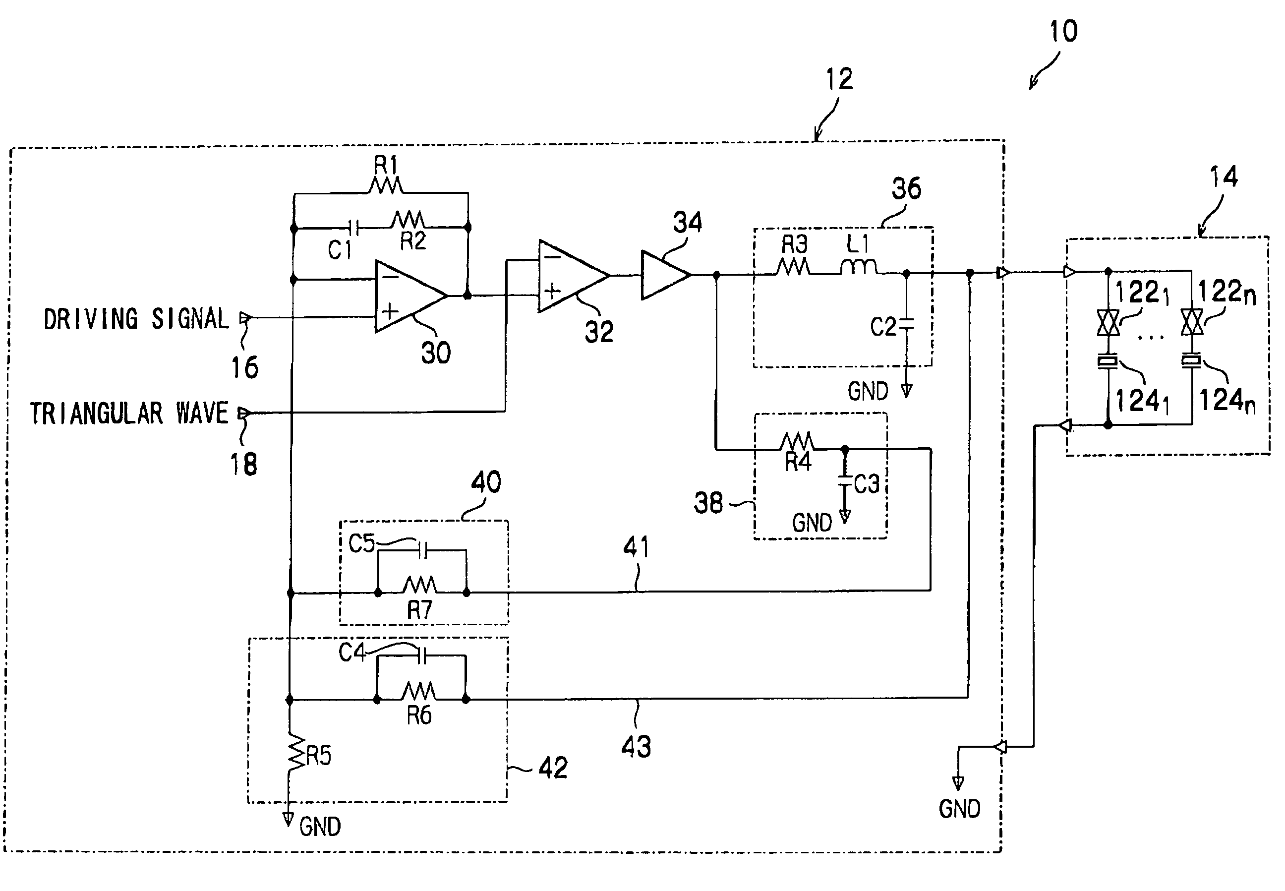
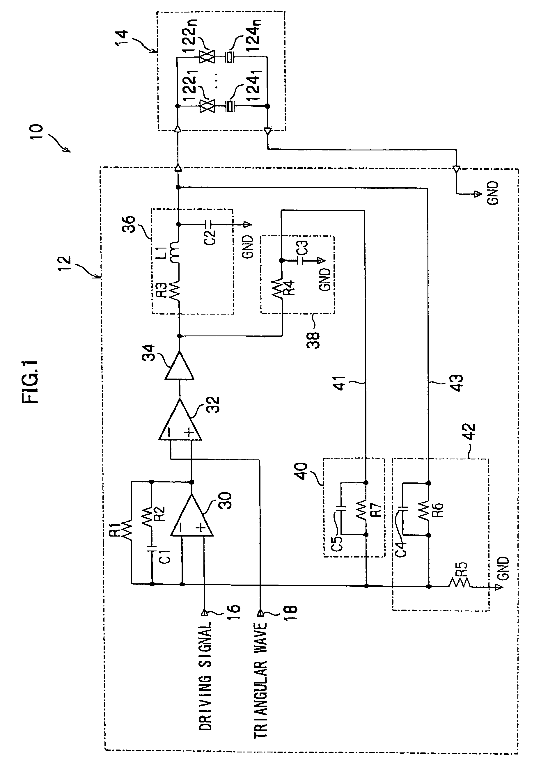
[0044]As shown in FIG. 1, an inkjet head driving circuit 10 of the present embodiment is structured with a driving circuit board 12 and a head 14. At the driving circuit board 12, an operational amplifier 30, a comparator 32, a digital power amplifier 34, a first filter 36, a second filter 38, a smoothing circuit 42 and a smoothing circuit 40 are formed. At the head 14, n (‘n’ being a natural number) transfer gates 1221 to 122n and n piezoelectric actuators 1241 to 124n, which are connected in respective series with the transfer gates 1221 to 122n, are provided.

[0045]A driving signal input terminal 16, at which an input signal is inputted, is connected to a non-inverting input terminal of the operational amplifier 30. An output terminal of the operational amplifier 30 is connected to a non-inverting input terminal of the comparator 32, which constitutes a pulse width modulator. The output terminal of the operational amplifier 30 is also connected to an inverting input terminal of th...

second embodiment

[0123]For the first embodiment, the inkjet head driving circuit 10 shown in FIG. 1 has been described. In this inkjet head driving circuit 10, the output terminal of the first filter 36 is connected, via the first feedback circuit 43 including the smoothing circuit 42, to the inverting input terminal of the operational amplifier 30 and the output terminal of the digital power amplifier 34 is connected via the second feedback circuit 41, which includes the second filter 38 and the smoothing circuit 40 structured by the resistor R7 and the capacitor C5 connected in parallel with the resistor R7, to the inverting input terminal of the operational amplifier 30. For the second embodiment, a case which further includes a third feedback circuit, which feeds back output of the first filter 36 through a wiring resistance to the inverting input terminal of the operational amplifier 30, will be described.

[0124]If a wiring resistance R9 between the driving circuit board 12 and the head 14 as sh...

third embodiment

[0130]FIG. 8 is a circuit diagram showing an inkjet head driving circuit 10A relating to the third embodiment. The inkjet head driving circuit 10A of the third embodiment is a circuit in which the second filter 38 is removed from the inkjet head driving circuit 10 shown in FIG. 1 and a first filter 36A is provided instead of the first filter 36. In FIG. 8, circuits that are the same as circuits shown in FIG. 1 are assigned the same reference numerals, and detailed descriptions thereof are omitted.

[0131]The first filter 36A is provided with the inductor L1, the resistor R3 and the capacitor C2. One terminal of the inductor L1 is connected to the output terminal of the digital power amplifier 34 and the other terminal of the inductor L1 is connected to the resistor R3. Another terminal of the resistor R3 (the terminal thereof that is not connected to the inductor L1) is connected to the capacitor C2 and the transfer gates 1221 to 122n of the head 14. Another terminal of the capacitor ...


PUM


Abstract

A capacitive load driving circuit which includes an operational amplifier, a pulse width modulator, a digital power amplifier, a first filter, a first feedback circuit and a second feedback circuit. The operational amplifier outputs a differential signal between a signal fed back to the inverting input terminal and an input signal inputted to the non-inverting input terminal. The pulse width modulator pulse width-modulates output from the operational amplifier and outputs a digital signal. The digital power amplifier amplifies power of the digital signal. The first filter smooths output of the digital power amplifier and inputs the smoothed signal to the capacitive load as the driving signal. The first feedback circuit feeds back the driving signal outputted from the first filter to the inverting input terminal of the operational amplifier. The second feedback circuit feeds back a signal outputted from the digital power amplifier, which signal includes a phase which is advanced relative to the driving signal, to the inverting input terminal of the operational amplifier.

Description

CROSS-REFERENCE TO RELATED APPLICATION[0001]This application claims priority under 35 USC 119 from Japanese Patent Application Nos. 2004-124400 and 2005-114953, the disclosures of which are incorporated by reference herein.BACKGROUND OF THE INVENTION[0002]1. Field of the Invention[0003]The present invention relates to a capacitive load driving circuit, a droplet ejection device, a droplet ejection unit and an inkjet head driving circuit, and more particularly relates to a capacitive load driving circuit, droplet ejection device, droplet ejection unit and inkjet head driving circuit for driving capacitive loads.[0004]2. Description of the Related Art[0005]Heretofore, inkjet head driving circuits have caused ink droplets to be ejected from nozzles of inkjet heads, which nozzles are provided in correspondence with piezoelectric actuators, by outputting analog driving signals to the piezoelectric actuators so as to discharge the ink droplets from the nozzles. In such an inkjet head driv...

Claims


Application Information

Patent Timeline
Patent Type & Authority Patents(United States)
IPC IPC(8): B41J29/38G05F1/40H02J1/00B41J2/045B41J2/055G05F1/10
CPCB41J2/04541B41J2/04548B41J2/04581B41J2/04591
Inventor ISHIZAKI, SUNAO
Owner FUJIFILM BUSINESS INNOVATION CORP
Why Eureka
Try Eureka