Drop volume measurement and control for ink jet printing

a technology of inkjet printing and measurement of drop volume, which is applied in the direction of printing, other printing apparatus, etc., can solve the problems of significant productivity decline, major defects in the end product, and inacceptable variations in current for the same driving voltag

Inactive Publication Date: 2006-10-17
DOLYA HOLDCO 5 LTD
View PDF7 Cites 75 Cited by
  • Summary
  • Abstract
  • Description
  • Claims
  • Application Information

AI Technical Summary

Problems solved by technology

Unintentional thickness variations and inhomogeneities may cause major defects in the end product.
Thus, small thickness variations often cause unacceptable variations in current for the same driving voltage.
Disadvantageously, the off-line method, as the name implies, requires that the particular dispenser or dispensers being tested are taken out of use while being tested.
The interruption of the printing process and the time consumption involved during testing can mean a significant decrease in productivity.
Additionally, if there is more than one nozzle, each nozzle must be tested separately, and so it is not efficient to perform a determination of drop volume variation between nozzles.
Furthermore, the evaporation of solvents in the droplets between the time the droplets leave the nozzle and the moment they are weighed can skew the results of the test.
Disadvantageously, stroboscopic measurement is inaccurate.
The visible border of a given droplet strongly depends on the illumination, camera settings, and other technical variations, making the results unreliable for many applications.
Laser measurements are generally more precise than stroboscopic measurements, but are also time-consuming and expensive.
Furthermore, the optical components (such as mirrors, lenses, light-sources) used for laser measurements may be too bulky for a given application.
The bulkiness of components is especially disadvantageous when attempting to implement a plurality of detectors that are capable of scanning a plurality of nozzles simultaneously.
Additionally, the laser source may introduce laser hazards.
Finally, liquid droplets having different components may have different absorption of light, thereby skewing the results.
Optical methods are also susceptible to being compromised by ink splashes and / or dirt in the environment.
In the “dirty” environment of printing, the performance of optical sensors can be compromised, necessitating frequent cleaning and / or replacement of parts.

Method used


Image

  • Drop volume measurement and control for ink jet printing
  • Drop volume measurement and control for ink jet printing
  • Drop volume measurement and control for ink jet printing

Examples


Embodiment Construction

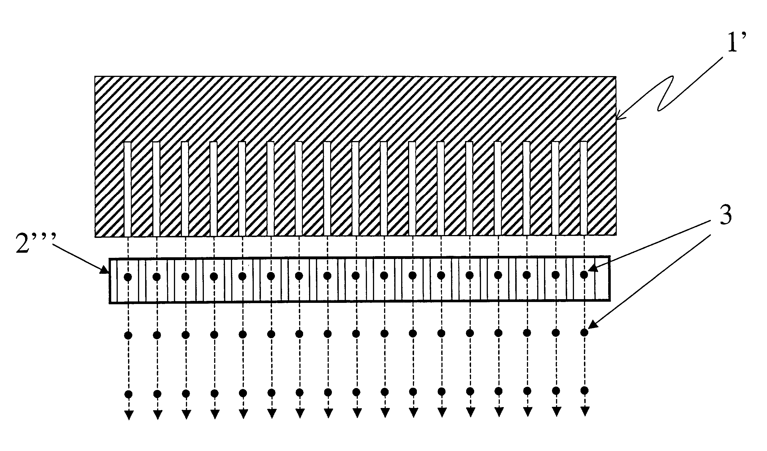
[0030]In a preferred embodiment, the invention is described in an implementation for the application of circuit and / or display components on substrates. The invention may be, in other preferred embodiments, implemented for other purposes, where drop volume is important in the application of droplets onto a surface. In a preferred embodiment described herein, the dielectric effect of such droplets is measured by an electrical circuit. In alternative preferred embodiments, other electrical / magnetic characteristics of droplets, such as resistance, electrical charge, or magnetic properties are measured.

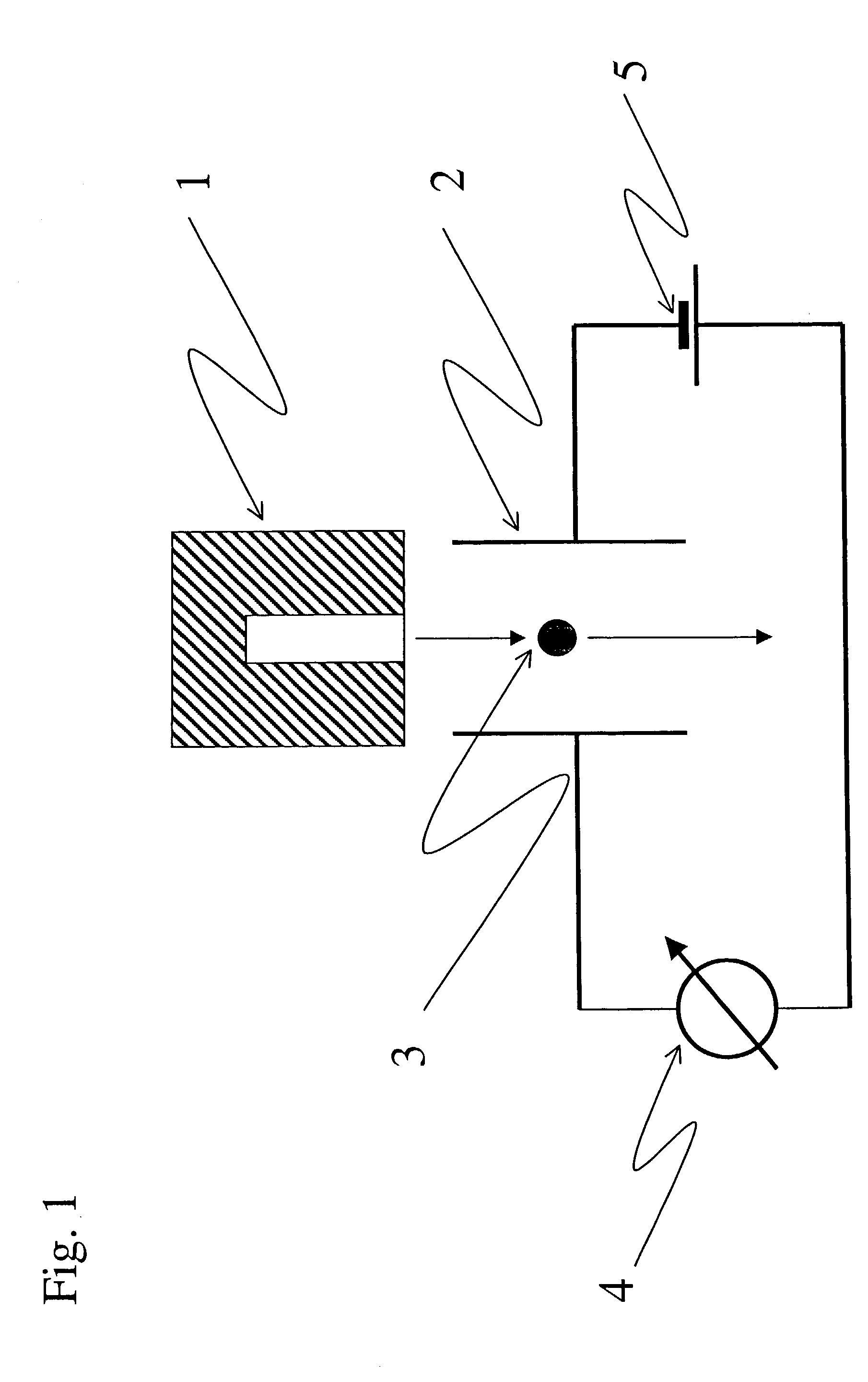
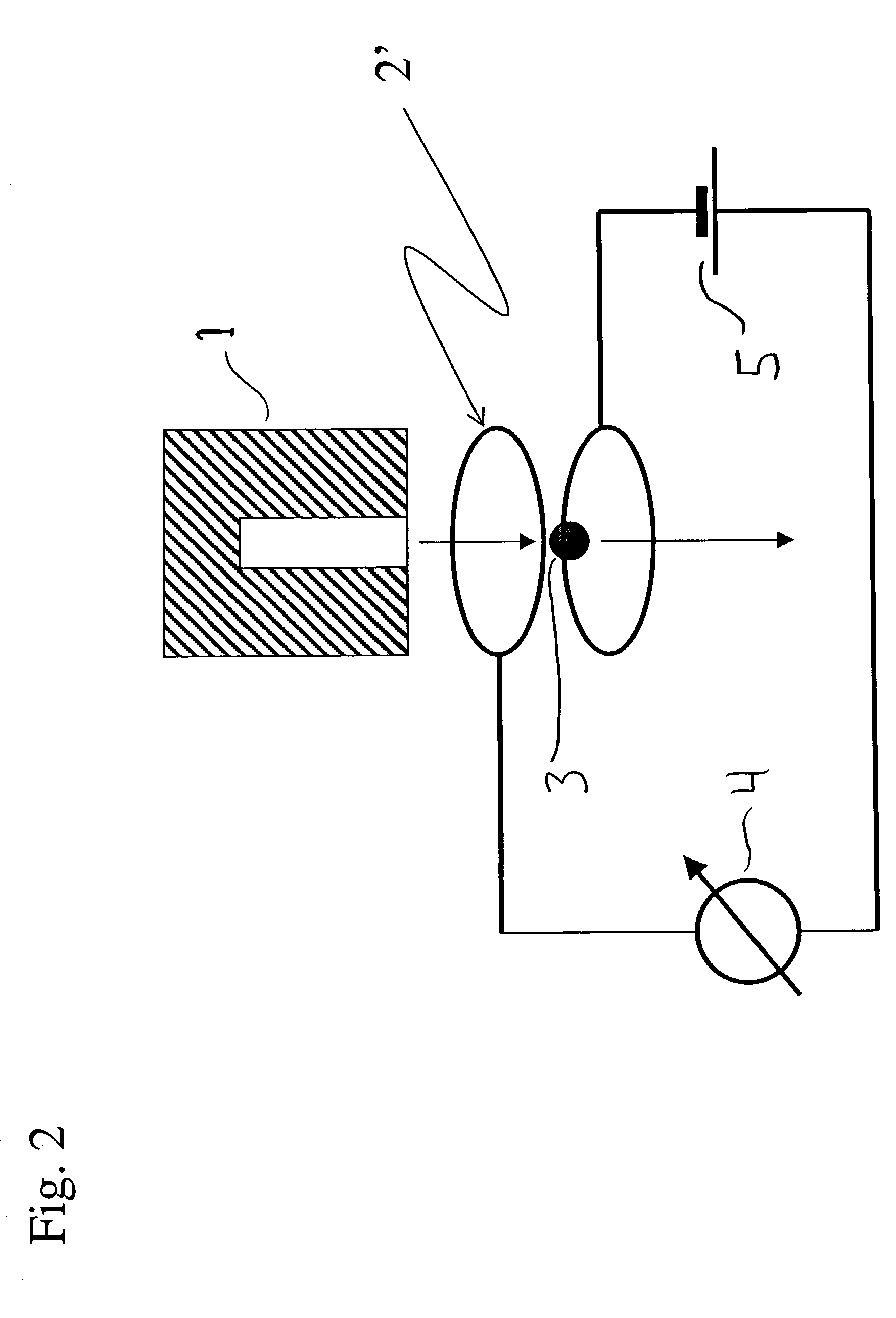
[0031]With reference to FIG. 1, a preferred embodiment of the invention is shown. Print head 1 for the purpose of this specification is any device that emits a liquid in a controlled fashion, using, by way of example only, a printing nozzle, printing plate, or dispensing nozzle. In a preferred embodiment shown in FIG. 1, print head 1 has a single nozzle.

[0032]Print head 1 emits, through c...


PUM


Abstract

A system and method is presented for measuring the volume of an ink-jet droplet or the relative volumes of a plurality of ink-jet droplets using their electrical properties. In a preferred embodiment a single small capacitor or an array of capacitors is used to measure the dielectric properties of ink-jet droplets and the absolute drop volumes are derived. In an alternative preferred embodiment the relative differences in drop volumes are determined. A feedback circuit, such as one using lock-in technique, may be used to automatically adjust subsequent drop volumes.

Description

BACKGROUND OF THE INVENTION[0001]1. Field of the Invention[0002]The present invention relates to a drop volume measurement and control mechanism and process for inkjet printing. More particularly, the present invention relates to the measurement of an electrical property of an ink-jet droplet, such as its dielectric properties, to determine its volume.[0003]2. Description of Related Art[0004]One conventional type of printer forms characters and images on a medium or substrate, such as paper, by expelling droplets of ink, often comprising organic material, in a controlled fashion so that the droplets land on the medium in a pattern. Such a printer can be conceptualized as a mechanism for moving and placing the medium in a position such that ink droplets can be placed on the medium, a printing cartridge which controls the flow of ink and expels droplets of ink to the medium, and appropriate control hardware and software. A conventional print cartridge for an inkjet type printer compri...

Claims


Application Information

Patent Timeline
Patent Type & Authority Patents(United States)
IPC IPC(8): B41J29/393B41J2/125
CPCB41J2/125
Inventor STOESSEL, MATTHIASPICHLER, KARL
Owner DOLYA HOLDCO 5 LTD
Why Eureka
Try Eureka