Variable lens

a variable lens and lens shape technology, applied in the field of variable lenses, can solve the problems of difficult to maintain good optical properties, difficult to obtain a range of desired lens shapes, and easy mechanical fatigue, and achieve the effect of different indices of refraction

Active Publication Date: 2007-11-27
KONINK PHILIPS ELECTRONICS NV
View PDF8 Cites 21 Cited by
  • Summary
  • Abstract
  • Description
  • Claims
  • Application Information

AI Technical Summary

Benefits of technology

[0015]The meniscus between the two fluids acts as a lens, and so the effective position of the lens can easily be adjusted by moving the meniscus. As no mechanical components are required within the optical path of the lens, then the optical path does not suffer from mechanical wear and tear. Further, the lens shape is not subject to a changing voltage, thus making the lens independent of non-uniformities in thickness or composition of the insulating layer. Also, there is no risk of charging of the insulating layer at high voltages.
[0016]In another aspect, the present invention provides an optical device comprising a variable lens, the lens comprising: a chamber defined by at least one side wall and having an optical axis extending longitudinally through the chamber; the chamber containing a first fluid and a second fluid in contact over a meniscus extending transverse the optical axis, the perimeter of the meniscus being constrained by said side wall, the fluids being substantially immiscible and having different indices of refraction; and at least one pump arranged to controllably alter the position of the meniscus along the optical axis by altering the relative volume of each of said fluids contained within the chamber.

Problems solved by technology

Due to the movement of the membrane surface, it is difficult to maintain good optical properties.
Further, it is susceptible to mechanical fatigue.
Consequently, obtaining a range of desired lens shapes can be problematic, particularly if the elasticity of the membrane 42 changes over time.
Further, flexible membranes are not normally gas tight, resulting in the evaporation of the fluid from the device over time.
Further, the insulating layer may suffer from charging (especially at high voltages).
If the insulating layer is charged unequally, this will lead to unequal contact angles, and thus to non-spherical lens.
Finally, as is also the problem with fixed focus lenses, if it is desirable to maintain the same shape lens, but simply alter the position of the lens, then the complete device must be mechanically moved e.g. by expensive actuators.
Such movement can be difficult to control accurately, and can be susceptible to vibrations and mechanical wear and tear.

Method used


Image

  • Variable lens
  • Variable lens
  • Variable lens

Examples


first embodiment

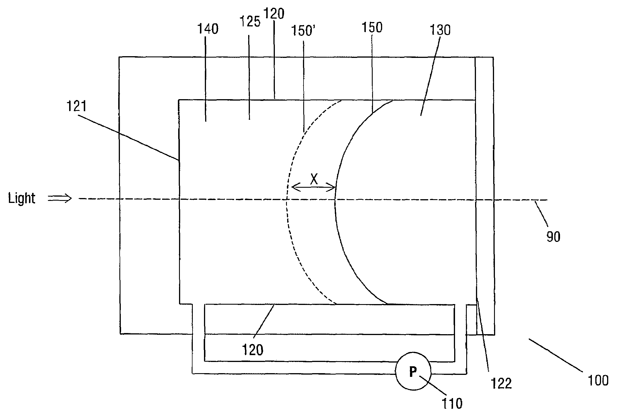
[0031]FIG. 3A shows a variable lens in accordance with the present invention. The lens 100 can be regarded as being formed of two distinct elements: a lens function formed by the meniscus 150 between two fluids 130, 140, and a pump 110 arranged to alter the position of the lens function.

[0032]A fluid is a substance that alters its shape in response to any force, that tends to flow or to conform to the outline of its chamber, and that includes gases, vapours, liquids and mixtures of solids and liquids capable of flow.

[0033]The two fluids 130, 140 are substantially immiscible i.e. the two fluids do not mix. The two fluids 130, 140 have different refractive indices. A lens function is thus provided by the meniscus 150 formed along the contact area of the two fluids, as the fluids have different refractive indices. A lens function is the ability of the meniscus 150 to focus (converge or diverge) one or more wavelengths of the light.

[0034]The two fluids are preferably of substantially eq...

second embodiment

[0043]FIG. 4 shows a variable lens 200 in accordance with the present invention. Identical reference numerals are utilized to indicate similar features. As previously, a chamber is defined by side walls 120. The chamber contains the meniscus 150 that forms the interface between two substantially immiscible fluids 130, 140. The position of the meniscus 150 relative to the optical axis 90 is controlled by a pump.

[0044]The lens 200 essentially corresponds to a conically shaped cylinder 123 (e.g. an outer chamber) containing a concentrically placed circular cylinder 124 (e.g. an inner chamber, which has inner surfaces in the form of side walls 120). The cylinder 124 has an open connection with the rest of the liquids in the conically shaped cylinder 123. In this embodiment, the first liquid 130 is a polar or conductive liquid (e.g. water, or water with a salt added to increase its conductivity), and fluid 140 is non-conductive (e.g. silicone oil or an alkane). Annular electrode 116 is p...


PUM

PropertyMeasurementUnit
angle of inclinationaaaaaaaaaa
inclination angleaaaaaaaaaa

Abstract

A variable lens includes a chamber defined by at least one side wall and has an optical axis extending longitudinally through the chamber. The chamber contains a first fluid and a second fluid contact over a meniscus extending transverse the optical axis. The perimeter of the meniscus is constrained by the side walls. The fluids are substantially immiscible, and have different indices of refraction. At least one pump is arranged to controllably alter the position of the meniscus along the optical axis by altering the relative volume of each of the fluids contained within the chamber.

Description

FIELD OF THE INVENTION[0001]The present invention relates to a variable lens, to optical devices including such a lens, and to methods of manufacturing such lenses and such devices.BACKGROUND OF THE INVENTION[0002]A lens is a device that can focus (converge or diverge) one or more wavelengths of light. The term light is understood to include both visible electromagnetic radiation, and other wavelengths of electromagnetic radiation.[0003]A variable (or adjustable) lens is a lens in which one or more properties of the lens can be controllably adjusted e.g. in which either the focal length or the position of the lens can be altered.[0004]DE 19710668 describes a variable lens system 40, as illustrated in FIGS. 1A and 1B. The lens system 40 comprises a resilient membrane 42 filled with a fluid 44. The pressure of the fluid 44 within the membrane is controlled by means of a pump 46. The dotted line illustrates the optical axis 90 of the lens system 40. The membrane 42 acts as a variable l...

Claims


Application Information

Patent Timeline
Patent Type & Authority Patents(United States)
IPC IPC(8): G02B1/06G02B3/12G02B3/14G02B26/02G11B7/00G11B7/135
CPCG02B3/14G02B26/005G11B7/1374G11B7/1376G11B2007/13727G11B2007/0006G11B2007/0013G02B3/12
Inventor KUIPER, STEINHENDRIKS, BERNARDUS HENDRIKUS WILHELMUS
Owner KONINK PHILIPS ELECTRONICS NV
Why Eureka
Try Eureka