Insert for Ultrasonic Burr-Drill Unit

US20070254262A1Active Publication Date: 2007-11-01SOC POUR LA CONCEPTION DES APPL DES TECHN ELECTRONIQUES SATELEC

Image

  • Insert for Ultrasonic Burr-Drill Unit
  • Insert for Ultrasonic Burr-Drill Unit
  • Insert for Ultrasonic Burr-Drill Unit

Examples


Embodiment Construction

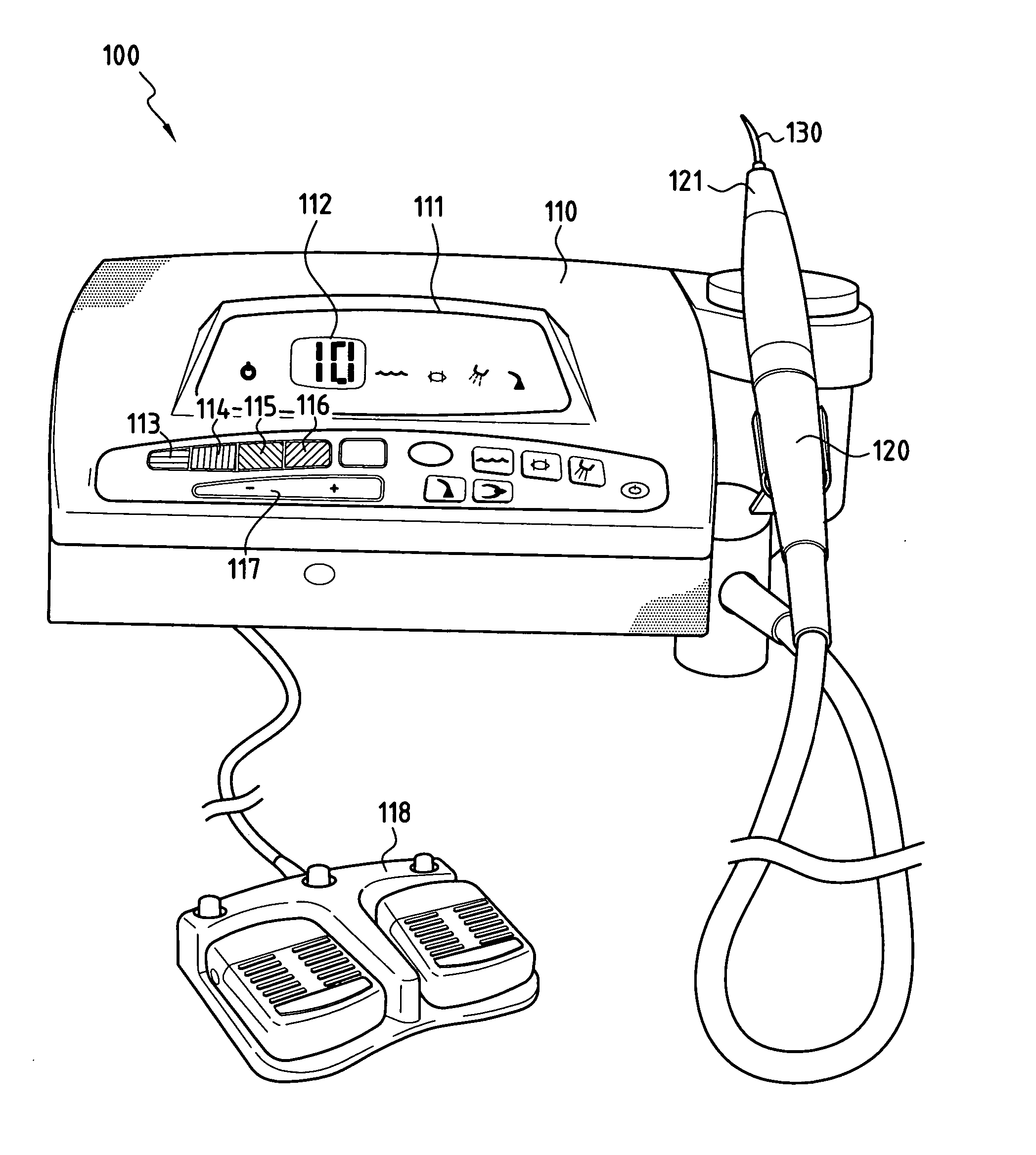
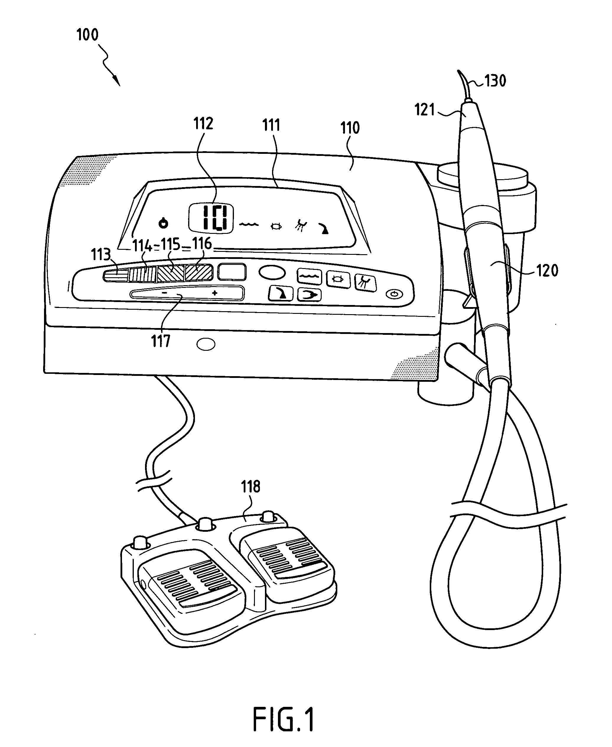
[0025]FIG. 1 shows an ultrasound scaler appliance 100 comprising an ultrasound generator 110 connected to a handpiece 120 that is fitted with a tip 130. In well-known manner, the handpiece 120 includes a transducer (not shown), e.g. constituted by a piezoelectric material and mechanically coupled to the tip 130 in such a manner as to transmit vibratory waves thereto, the amplitude of the waves being determined as a function of the power delivered by the ultrasound generator 110.

[0026] The generator includes display means 111 and a series of keys 113 to 116, each corresponding to a determined power range. By way of example, the key 113, shaded in FIG. 1 with horizontal lines, corresponds to the lowest power and amplitude configuration, e.g. recommended for delicate treatment of fragile surfaces with very fine tips. The key 114, identified in FIG. 1 by vertical shading, corresponds to a medium power and amplitude range adapted for endodontonic applications using tips of thin and elon...


PUM


Abstract

In order to select the ultrasonic wave power and amplitude range that matches an ultrasonic tip (130) for mounting on a surgical handpiece (120), the tip (130) includes a cavity (131) forming a housing for an identifier element (140). The identifier element is made of an elastic material presenting a melting temperature higher than 130° C. enabling it to withstand both vibration and sterilization temperatures. The identifier element (140) presents a color or a pattern corresponding to the ultrasonic wave power and amplitude range appropriate for use with the tip.

Description

BACKGROUND OF THE INVENTION [0001] The present invention relates to appliances for dental treatment, and more particularly to ultrasonic appliances such as scaler appliances comprising instruments that vibrate at ultrasonic frequencies. [0002] This type of appliance essentially comprises a handpiece including a transducer mechanically coupled to a vibrating instrument referred to as an “tip” or a “sonotrode”, with the handpiece being connected to an ultrasound generator. [0003] The tip is an interchangeable piece that presents a wide variety of shapes depending on the treatment for which it is intended. Examples of such tips are described in particular in U.S. Pat. Nos. 6,312,256 and 4,283,175. The amplitude or the power of the ultrasonic waves transmitted by the generator also depends on the type of treatment that is to be carried out. For example, for periodontal debridement, the required power / amplitude is well below that needed for removing scale (“scaling”). Similarly, the type...

Claims


Application Information

Patent Timeline
01 Nov 2007
Publication
US20070254262A1
IPC
A61C3/03; A61C17/20
CPC
A61B2019/444; A61C2201/002; A61C3/03; A61B90/92; A61C17/20
Inventors
DOUSSIN, JEAN-CLAUDE; GANGNEUX, PHILIPPE