Precoding method for transmitting information in a MIMO radio system

Inactive Publication Date: 2007-11-01
NOKIA CORP
View PDF7 Cites 27 Cited by
  • Summary
  • Abstract
  • Description
  • Claims
  • Application Information

AI Technical Summary

Benefits of technology

[0013]Different embodiments of the invention provide several advantages. Multi-user interference is considerably reduced at the transmitter and significant impro

Problems solved by technology

However, the techniques proposed so far rely on ad-hoc designs stemming from the single rece

Method used


Image

  • Precoding method for transmitting information in a MIMO radio system
  • Precoding method for transmitting information in a MIMO radio system
  • Precoding method for transmitting information in a MIMO radio system

Examples


Embodiment Construction

[0021]The present invention is applicable to various different digital radio systems where mechanisms for channel state information are available, for example, TDMA, FDMA, CDMA radio systems, and different variants of them. The invention is especially suited for time division duplexing (TDD) systems. In the following, an advantageous embodiment of the data transmission system according to the invention is described in a configuration of a mobile communication system, without limiting the invention to the embodied radio system or the specific terms and elements used in the description.

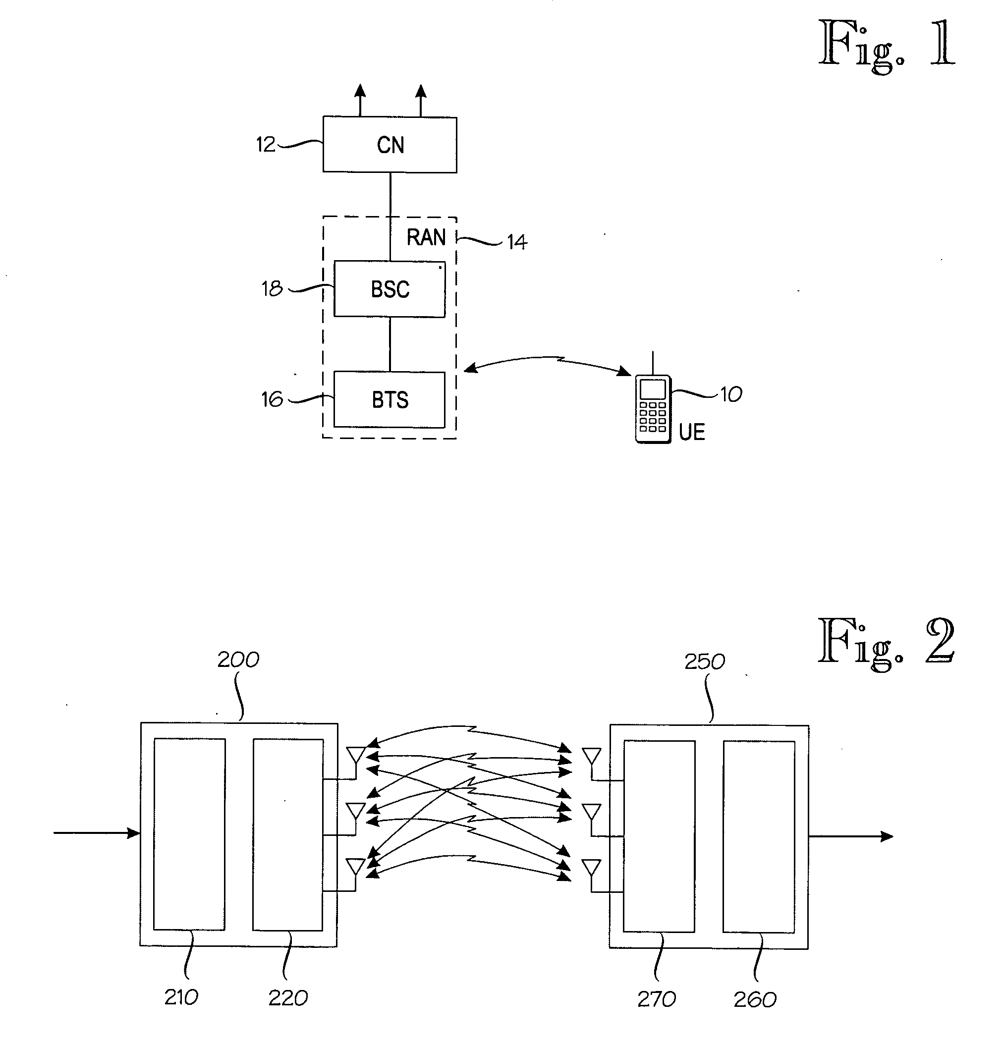
[0022]FIG. 1 illustrates user equipment 10 that is connected to the Core Network (CN) 12 through a Radio Access Network (RAN) 14. In radio access network, coverage area of base transceiver stations (BTS) 16 that belong to the same base station form a cell. The user may move from one cell to another, and the network hands the user over to a different cell according to the movement. Each base station comp...


PUM


Abstract

A method of transmitting a transmit vector comprising symbols to be delivered within a resource unit from a transmitting station with one or more transmit antennas to one or more receiving stations with one or more receive antennas. The method comprises obtaining information on the state of channels between the one or more transmit antennas and the one or more receive antennas; and computing, on the basis of the channel states between the one or more transmit antennas and the one or more receive antennas, a covariance matrix Rnn, a combined channel matrix H, and a block-diagonal linear operator V of decoding matrices of the receiving stations. The transmit vector is multiplied with a precoding matrix P fulfilling the equations
(HHVHVH=λI)P=HHVH
Vi(HiPPHHiH+Rnn,k)=PiHHiH
trace(PHP)=Ptr
and corresponding performing filtering in the receiving station using a receiver filter corresponding to the block-diagonal linear operator V.

Description

FIELD OF THE INVENTION[0001]The present invention relates to communications and more particularly to a method of transmitting a transmit vector comprising symbols to be delivered within a resource unit from a transmitting station with one or more transmit antennas to one or more receiving stations with one or more receive antennas, to a radio system, to a signal processing unit, to a transmitting station, to a computer program product and to a computer program distribution medium.BACKGROUND OF THE INVENTION[0002]The invention is related to utilization of multi-user channel, where a single transmitting station sends data to several receiving stations within the same resource unit. If a transmitting station has several antennas, it is possible to separate the users only by using the spatial properties of the channel. This results to significantly enhanced system throughput since the users do not have to be separated in time, frequency or code domain.[0003]Recently, multiple input, mul...

Claims


Application Information

Patent Timeline
IPC IPC(8): H04B1/02H04M1/00
CPCH04B7/0413H04L25/03343H04B7/0465H04L2025/03802H04L2025/03426H04B7/0417H04B7/0626H04B7/086H04B7/02H04L27/26
Inventor BANDEMER, BERNDVISURI, SAMULI
Owner NOKIA CORP
Why Eureka
Try Eureka