
Radio communication system

a radio communication system and radio frequency technology, applied in the field of radio communication systems, can solve the problems of inability to demodulate high-precision data, the accuracy of channel estimation is worsened for the 2 ghz band, and the estimation precision is worsened, so as to improve the accuracy of channel estimation at each frequency, improve the accuracy of channel estimation, and improve the effect of reception performance and transmission efficiency

Inactive Publication Date: 2007-11-01
FUJITSU LTD
View PDF19 Cites 43 Cited by
  • Summary
  • Abstract
  • Description
  • Claims
  • Application Information

AI Technical Summary

Benefits of technology

[0022] In light of the above, an object of the invention is, in a multiple-band radio communication system and a multicarrier radio communication system, to improve the reception performance, and moreover the transmission efficiency, in each band or at each frequency.
[0023] A further object of the invention is to improve the channel estimation precision and improve the reception performance at each frequency, and enhance transmission efficiency, by changing the lengths of pilots inserted at each frequency.
[0024] A further object of the invention is to reduce intersymbol interference and improve reception performance in each band or at each frequency, and enhance transmission efficiency, by changing the lengths of guard intervals inserted in each band or at each frequency.

Problems solved by technology

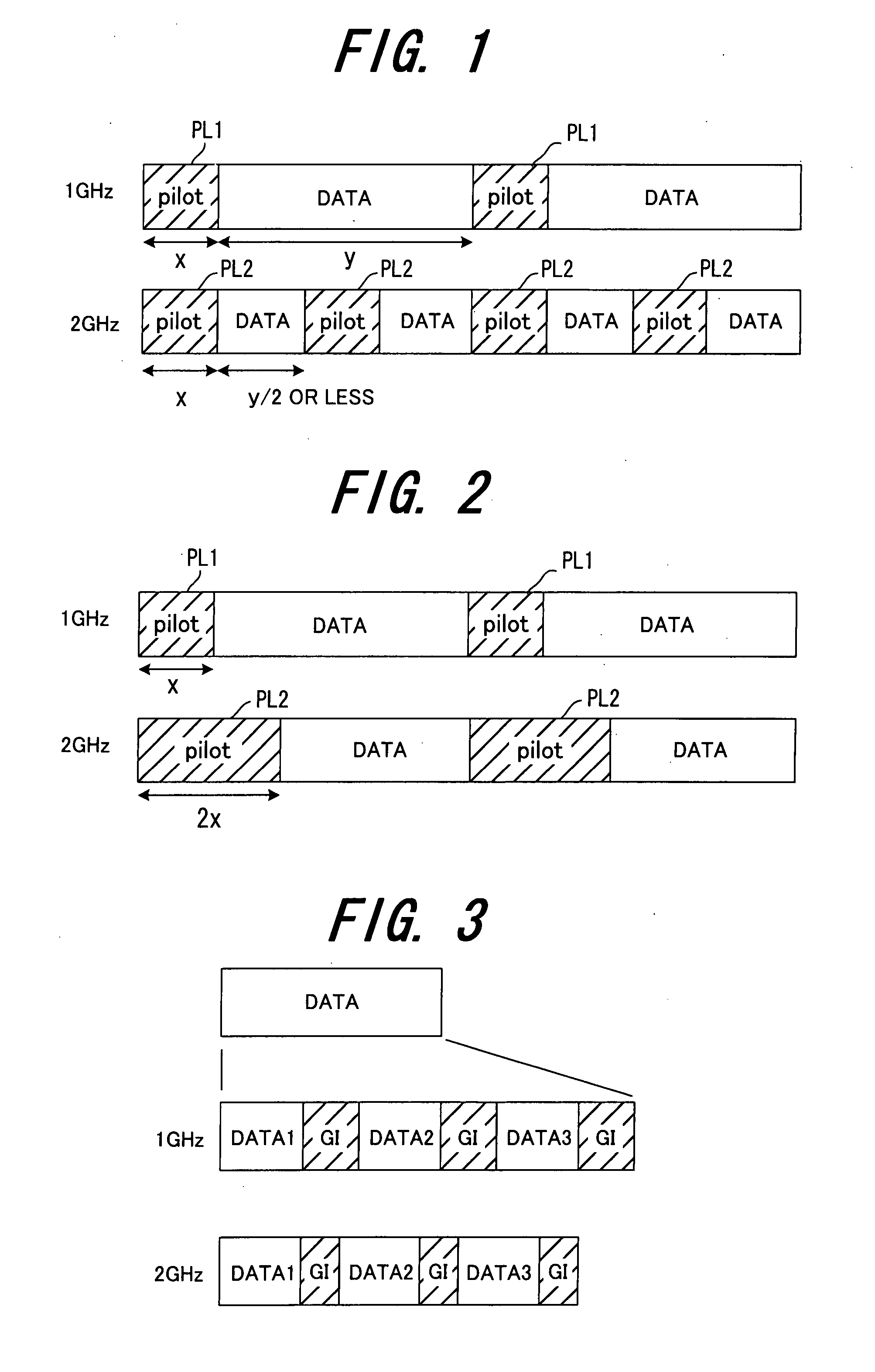
However, in the prior art, as shown in FIG. 16, the lengths of the pilots PL1, PL2 interpolated into the data DT1, DT2 regardless of frequency band are the same, and so there has been the problem that the channel estimation precision is worsened for the 2 GHz band.
Hence when demodulating data transmitted at 2 GHz, the channel estimation precision is worsened, and so high-precision data demodulation is not possible.
From the above, in the 2 GHz band the guard intervals are too long, that is, there is the problem that transmission efficiency is worsened by providing excess guard interval length.
As a result, the guard intervals are too long at 2 GHz, and transmission efficiency is worsened.
In this OFDM transmission method, as explained above, there is frequency fluctuation due to multipath fading, and when the orthogonality between subcarriers is degraded, performance deteriorates.
However, these technologies of the prior art do not improve the reception performance in each band or at each frequency in a multiple-band radio communication system or in a multicarrier radio communication system.

Method used


Image

  • Radio communication system
  • Radio communication system
  • Radio communication system

Examples


first embodiment

[0072] (B) First Embodiment

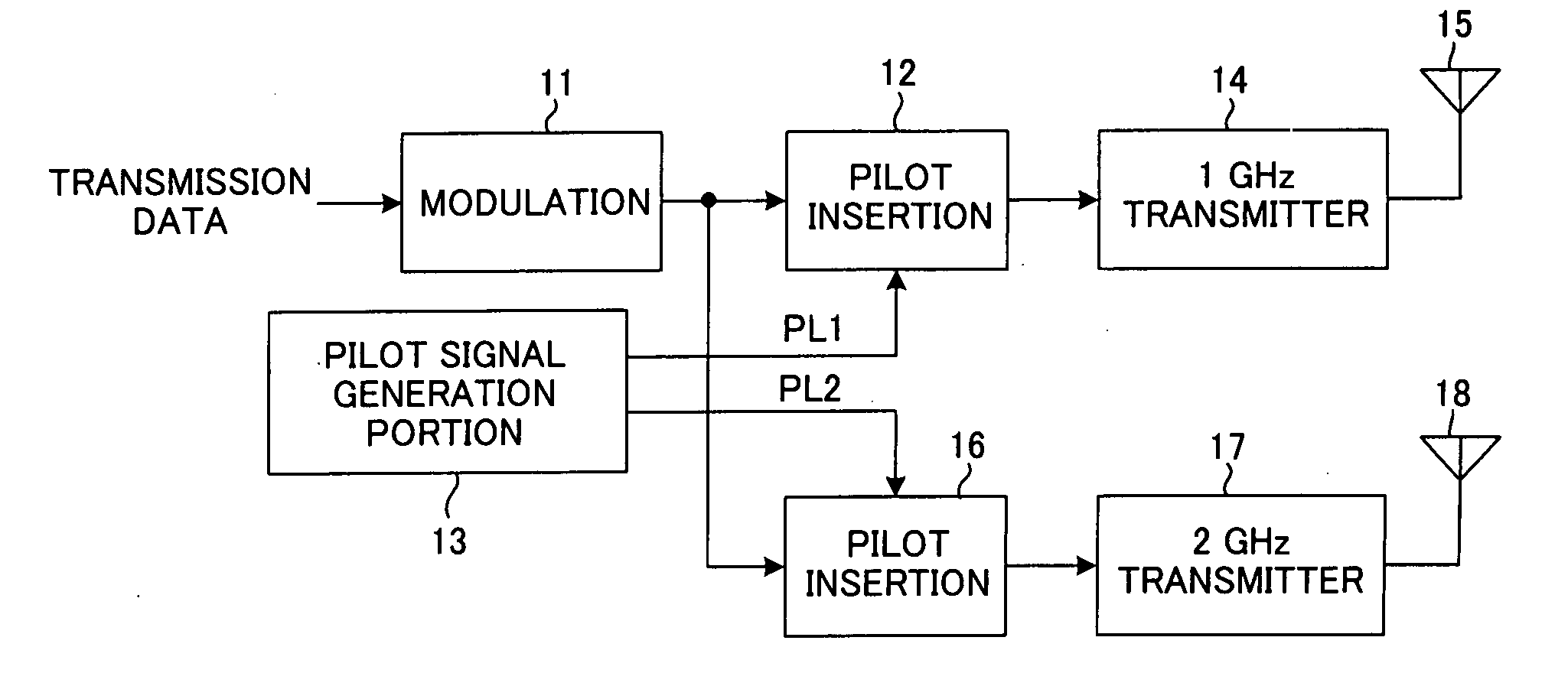
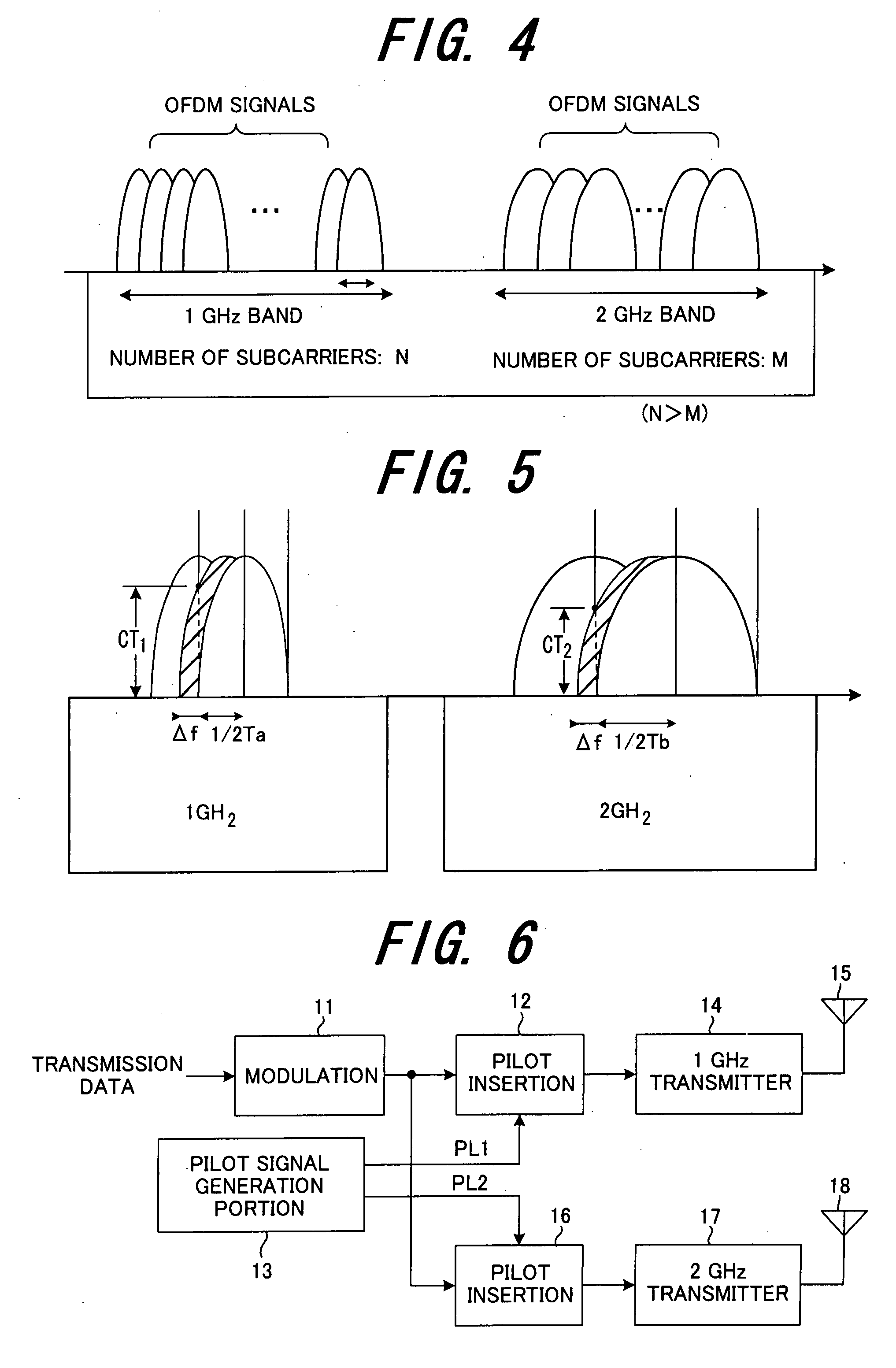
[0073]FIG. 6 shows the configuration of the transmission apparatus of a first embodiment, in a radio communication system using a plurality of different radio frequencies, in which pilot lengths are made different for each radio frequency; FIG. 7 shows the configuration of a reception apparatus.

[0074] In the transmission apparatus, the modulation portion 11 performs for example QPSK modulation of the transmission data, the first pilot insertion portion 12 inserts pilot signals PL1 for 1 GHz (see FIG. 1 and FIG. 2) generated by the pilot generation portion 13 into the QPSK in-phase component and quadrature component, and the 1 GHz transmitter 14 up-converts the frequency of the signals with the pilots PL1 inserted to 1 GHz and transmits the signals from the antenna 15. The second pilot insertion portion 16 inserts pilot signals PL2 for 2 GHz (see FIG. 1 and FIG. 2) generated by the pilot generation portion 13 into the QPSK in-phase component and quadrature...

second embodiment

[0078] (C) Second Embodiment

[0079]FIG. 9 shows the configuration of the transmission apparatus in a second embodiment in which guard interval lengths are made different in each band, in a radio communication system in which OFDM transmission is performed in each of a plurality of bands; FIG. 10 shows the configuration of a reception apparatus.

[0080] In the transmission apparatus, the serial / parallel conversion portion 31a of the multicarrier modulation portion 31 performs parallel conversion into N-symbols of the transmission data, the IFFT portion 31b performs IFFT processing as N subcarrier components of each of the parallel data symbols, and the parallel / serial conversion portion 31c converts the N-symbols of IFFT processing results (OFDM symbols) into series data as a OFDM symbol, which is output. The first guard interval addition portion 32 adds a guard interval (see FIG. 3) of the length for 1 GHz designated by the GI length designation portion 33 to the N-symbols (OFDM symbo...

third embodiment

[0085] (D) Third Embodiment

[0086]FIG. 13 shows the configuration of a transmission apparatus in third embodiment, in a radio communication system which performs OFDM transmission in each of a plurality of bands, in which the number of subcarriers is made different and the subcarrier interval is made different in each band; FIG. 14 shows the configuration of a reception apparatus.

[0087] The modulation portion 61 performs for example QPSK modulation of transmission data and outputs complex data. In the first multicarrier modulation portion 62, the serial / parallel conversion portion 62a converts the transmission data into N parallel data symbols, the IFFT portion 62b performs IFFT processing of the parallel data symbols as N subcarrier components, and a parallel / serial conversion portion, not shown, converts the N-symbol IFFT processing result (OFDM symbol) into serial data, which is output. The first guard interval addition portion 63 adds a guard interval of prescribed length to the...


PUM


Abstract

In a radio communication system in which multiple bands or a plurality of different radio frequencies are used, a different radio transmission method is used in each band or at each radio frequency. For example, by transmitting data using radio formats which are different in each band or at each radio frequency, the radio transmission method is made different in each band or at each radio frequency. In order to vary the radio format, (1) the pilot length is varied at each radio frequency; or (2) the pilot interval is varied at each radio frequency; or (3) the guard interval length is varied in each band or at each radio frequency; or (4) when multicarrier modulation is used for radio communication in each band, the subcarrier interval for multicarrier transmission is varied in each band.

Description

BACKGROUND OF THE INVENTION [0001] The present invention relates to a radio communication system which uses multiple bands or a plurality of different radio frequencies, and in particular relates to a radio communication system, and a transmission apparatus and reception apparatus, which use different radio transmission methods (radio transmission parameters) for each band or radio frequency. [0002] Second-generation mobile telephone systems use a plurality of frequency bands, such as the 800 MHz band and the 1.5 GHz band. And, in the IMT-2000 third-generation mobile telephone system, currently the 2 GHz band is being used, but usage of the 800 MHz band in the near future is also being studied. Thus the use of a plurality of frequency bands in a single mobile telephone system is a well-known fact. [0003] In a multiple-band radio communication system, that is, a radio communication system using a plurality of bandwidths (bands), or in a multi-carrier radio communication system using ...

Claims


Application Information

Patent Timeline
Patent Type & Authority Applications(United States)
IPC IPC(8): H04B1/02H04B7/08H04M1/00H04W28/06H04W48/18
CPCH04B7/2621H04B1/005H04L27/2602H04L27/26025H04B1/0064H04L27/2649H04L27/2626
Inventor FURUKAWA, HIDETO
Owner FUJITSU LTD
Learn More