User interface for automatic multi-plane imaging ultrasound system

a multi-plane, ultrasound system technology, applied in tomography, applications, instruments, etc., can solve the problems of inability to review previously considered view positions or exchange view positions, and conventional ultrasound systems have certain limitations

Inactive Publication Date: 2007-11-01
GENERAL ELECTRIC CO
View PDF7 Cites 98 Cited by
  • Summary
  • Abstract
  • Description
  • Claims
  • Application Information

AI Technical Summary

Benefits of technology

[0005] A need remains for an improved method and system that affords an easy mechanism to return to previously viewed positions, and g

Problems solved by technology

However, conventional ultrasound systems have experience certain limitations.
While the conventional automated multiplanar imaging process permits a user

Method used


Image

  • User interface for automatic multi-plane imaging ultrasound system
  • User interface for automatic multi-plane imaging ultrasound system
  • User interface for automatic multi-plane imaging ultrasound system

Examples


Embodiment Construction

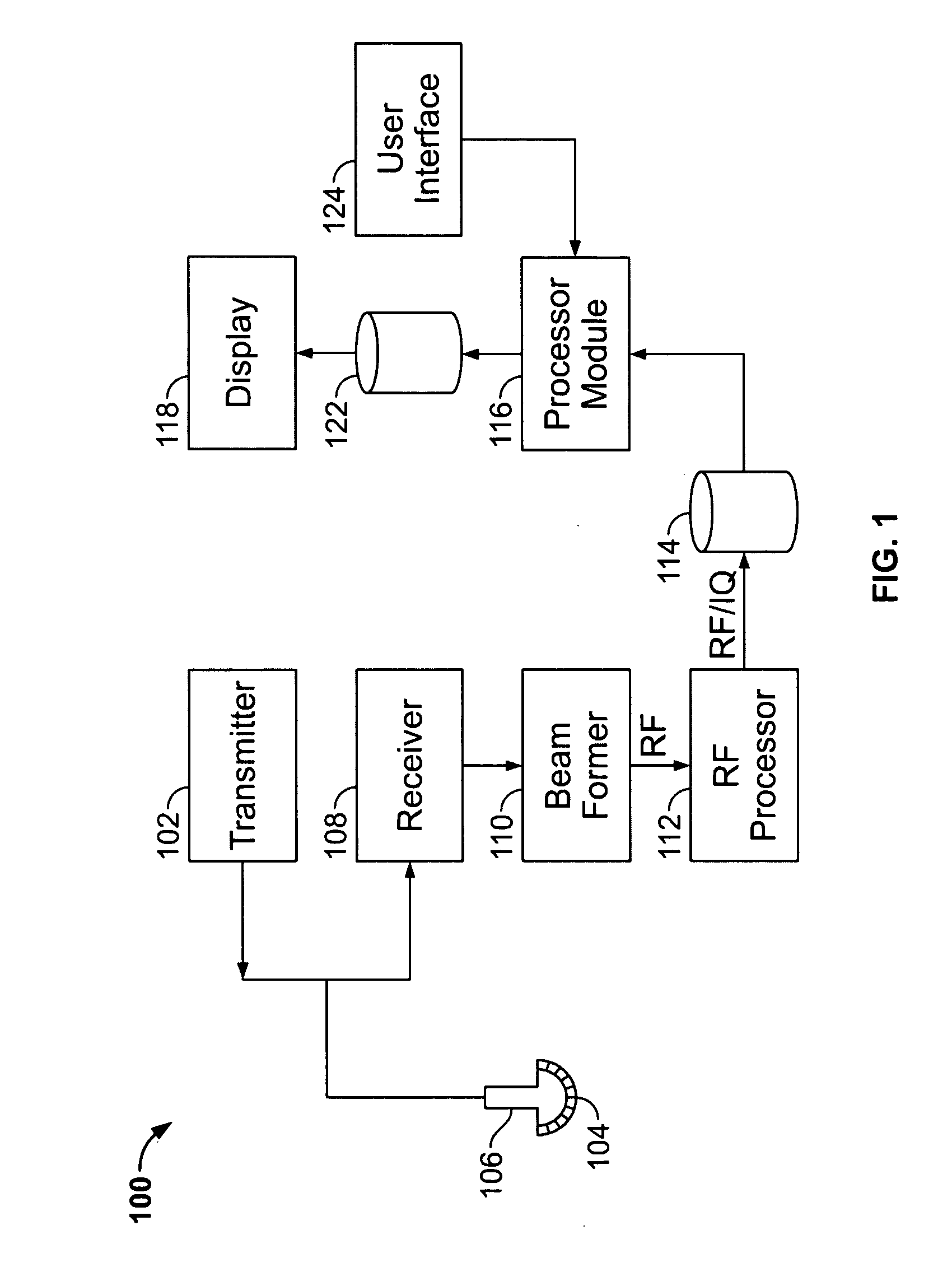
[0020]FIG. 1 illustrates a block diagram of an ultrasound system 100 formed in accordance with an embodiment of the present invention. The ultrasound system 100 includes a transmitter 102 which drives an array of elements 104 within a transducer 106 to emit pulsed ultrasonic signals into a body. A variety of geometries may be used. The ultrasonic signals are back-scattered from structures in the body, like blood cells or muscular tissue, to produce echoes which return to the elements 104. The echoes are received by a receiver 108. The received echoes are passed through a beamformer 110, which performs beamforming and outputs an RF signal. The RF signal then passes through an RF processor 112. Alternatively, the RF processor 112 may include a complex demodulator (not shown) that demodulates the RF signal to form IQ data pairs representative of the echo signals. The RF or IQ signal data may then be routed directly to memory 114 for storage.

[0021] The ultrasound system 100 also includ...


PUM


Abstract

A diagnostic ultrasound system is provided for automatically displaying multiple planes from a 3-D ultrasound data set. The system comprises a user interface for designating a reference plane, wherein the user interface provides a safe view position option and a restore reference plane option. A processor module maps the reference plane into a 3D ultrasound data set and automatically calculates image planes based on the reference plane for a current view position and a prior view position. A display is provided to selectively display the image planes associated with the current and prior reference planes. Memory stores the prior reference plane in response to selection of the save reference plane option, while the display switches from display of the current reference plane to restore the prior reference plane in response to selection of the restore reference plane option. Optionally, the memory may store coordinates in connection with the current and prior reference planes.

Description

RELATED APPLICATION [0001] The present application relates to and claims priority from Provisional Application Ser. No. 60 / 795,535 filed Apr. 27, 2006 titled “USER INTERFACE FOR AUTOMATIC MULTI-PLANE IMAGING ULTRASOUND SYSTEM”, the complete subject matter of which is hereby expressly incorporated in its entirety.BACKGROUND OF THE INVENTION [0002] Embodiments of the present invention relate generally to systems and methods for automatically displaying multiple planes from 3-D ultrasound data sets, and more specifically for providing a user interface that affords an easy exchange and restoration of prior view positions. [0003] Ultrasound systems are used in a variety of applications and by individuals with varied levels of skill. In many examinations, operators of the ultrasound system review select combinations of ultrasound images in accordance with predetermined protocols. In order to obtain the desired combination of ultrasound images, the operator steps through a sequence of oper...

Claims


Application Information

Patent Timeline
IPC IPC(8): A61B8/00G06K9/00
CPCA61B8/14A61B8/467A61B8/483A61B8/523G01S7/52074G06T2219/028G01S15/8993G03B42/06G06T19/00G06T2210/41G06T2219/008G01S7/52084A61B8/465A61B8/466
Inventor DESCHINGER, HARALDFALKENSAMMER, PETERGABEDER, FRANZ
Owner GENERAL ELECTRIC CO
Why Eureka
Try Eureka