Low pressure sample collection apparatus

a collection apparatus and low pressure technology, applied in the field of material sample collection, can solve the problems of sample contamination risk and sample contamination danger, and achieve the effect of facilitating sample collection and promoting sample drying

Inactive Publication Date: 2007-11-01
BODE TECH GROUP
View PDF13 Cites 48 Cited by
  • Summary
  • Abstract
  • Description
  • Claims
  • Application Information

AI Technical Summary

Benefits of technology

[0006]The device provides an improved low pressure sample collection apparatus for collecting samples of substances and protecting such samples from contamination prior to laboratory analysis. Generally, the sample collection apparatus includes a swab assembly including an elongated shaft, a swab member secured to an end of the shaft, and a cap member connected to an end of the shaft opposite the swab member. The cap member has plug members on opposite sides of a central portion thereof to enable the cap member to be plugged into a container member either with the swab member exposed or with the swab member positioned within and protected from contamination within the container member. The cap member may be provided with one or more bores to allow the influx of drying air into the container with the swab member therein to promote drying of a sample on the swab member. Preferably, the shaft is tubular and the cap member has a nipple on a side opposite from the shaft for connection of a low pressure vacuum source to establish an inflow of air through the swab member to thereby facilitate collection of samples onto and within the swab member.

Problems solved by technology

A problem with conventional swabs is that there is a danger of contamination of the sample if it is necessary to put the swab down, for example, to open a bag or container in which the swab will be placed.
Also, if it is necessary to set the swab down to dry, in a propped up condition or extending over the edge of a table, there is a risk of contamination of the sample.

Method used


Image

  • Low pressure sample collection apparatus
  • Low pressure sample collection apparatus
  • Low pressure sample collection apparatus

Examples


Embodiment Construction

[0025]As required, detailed embodiments of the present invention are disclosed herein; however, it is to be understood that the disclosed embodiments are merely exemplary of the invention, which may be embodied in various forms. Therefore, specific structural and functional details disclosed herein are not to be interpreted as limiting, but merely as a basis for the claims and as a representative basis for teaching one skilled in the art to variously employ the present invention in virtually any appropriately detailed structure.

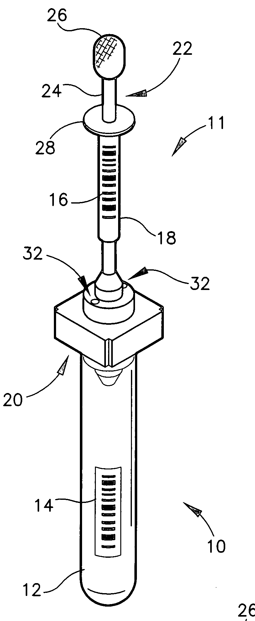
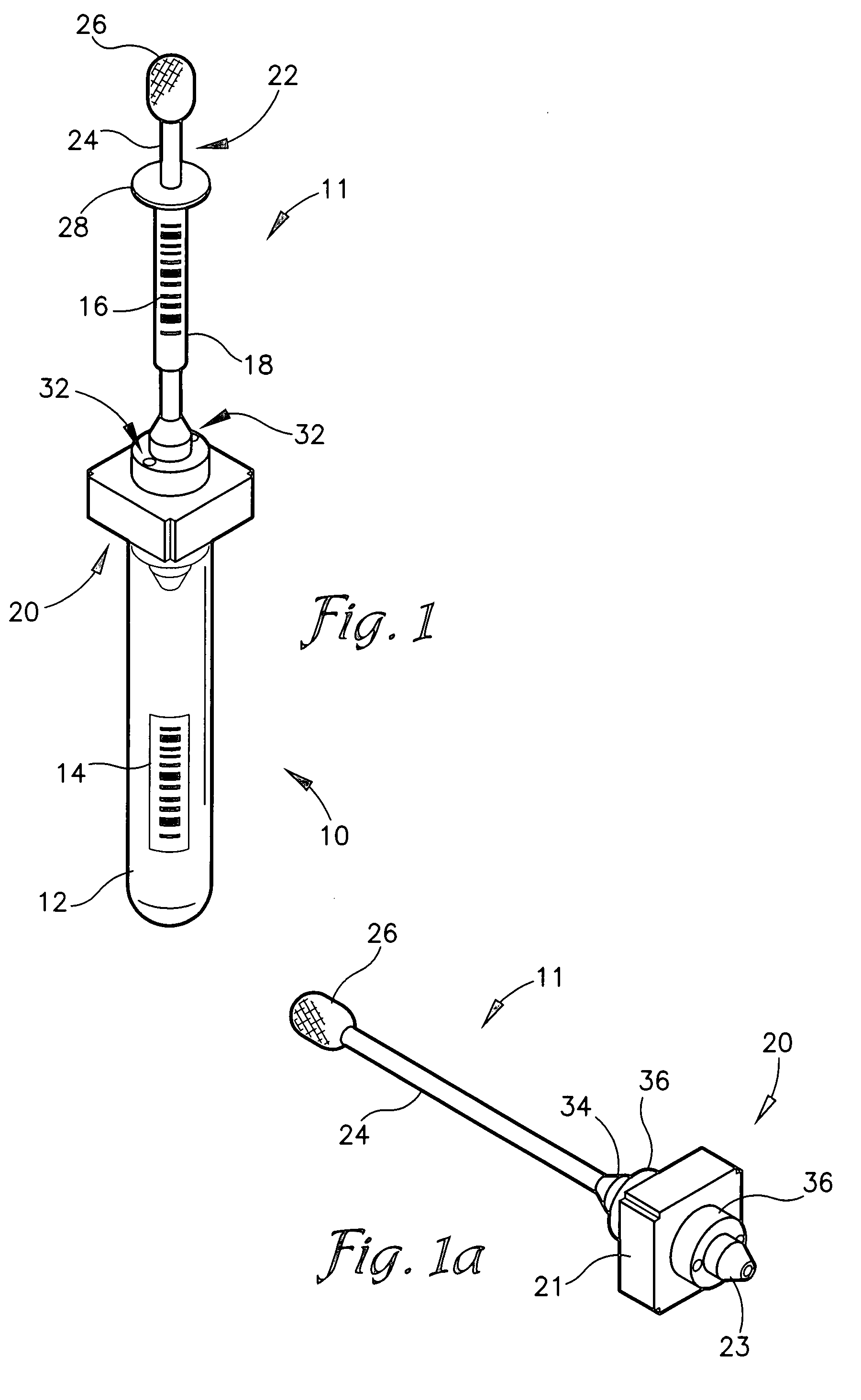
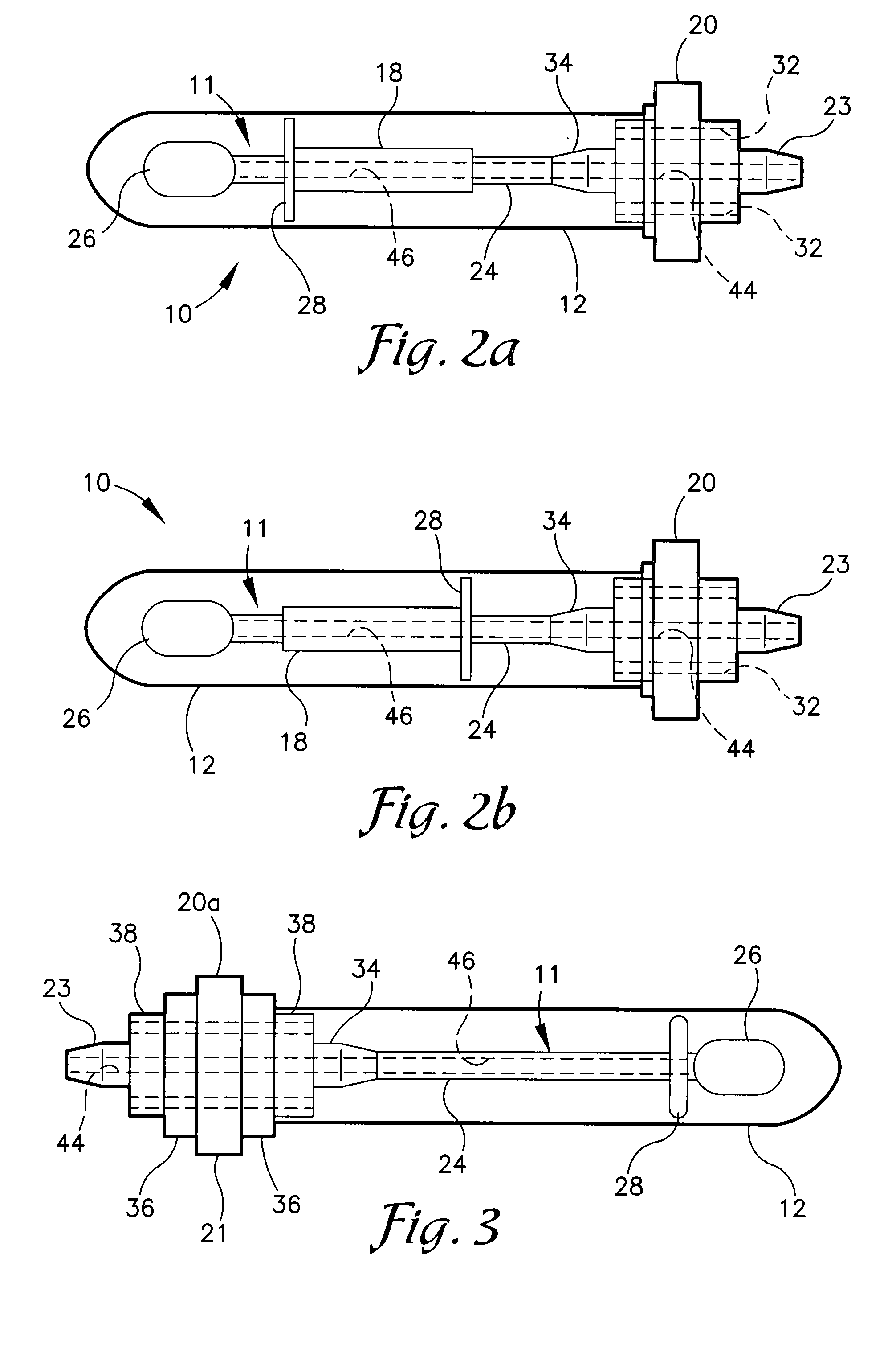
[0026]Referring now to the drawing figures, the reference numeral 10 generally designates a low pressure sample collection apparatus. The apparatus 10 generally includes a swab assembly 11 and a container member 12. As will be described below, the swab assembly 11 can be engaged with the container 12 in such a manner as to use the container 12 as a handle or as an enclosure to protect the swab assembly 11.

[0027]Referring to FIG. 1, the swab assembly 11 includ...


PUM


Abstract

A low pressure sample collection apparatus includes a double-ended cap member having similarly sized plug members extending from opposite sides, a vacuum connection nipple on one side and a shaft connection portion one the opposite, a passage extending through the cap from the nipple to the shaft connection portion, a tubular shaft connected to the shaft connection portion and having a sample collection swab member secured to an outer end thereof, and a container member having one end closed and an opposite end open. The cap member is reversibly plugged into the container either to use the container as a handle or to position the swab within the container for protection. A vacuum source may be connected to the assembly to draw air through the swab. The shaft may have a barrel telescoped thereon for separation of the swab from the shaft without contacting the swab.

Description

CROSS-REFERENCE TO RELATED APPLICATION[0001]This application claims priority under 35 U.S.C. 119(e) and 37 C.F.R. 1.78(a)(4) based upon copending U.S. Provisional Application Ser. No. 60 / 792,057 for LOW PRESSURE COLLECTION APPARATUS, filed Apr. 14, 2006, which is incorporated herein by reference.BACKGROUND OF THE INVENTION[0002]The present invention relates to the collection of material samples, as for forensic, scientific, or diagnostic purposes, and more particularly, to devices for collecting such samples and preserving them from contamination prior to laboratory analysis.[0003]Crime scene evidence is collected to establish facts related to a crime or a suspected crime and for identification and / or elimination of suspects and may be presented at a trial for the determination of guilt or innocence of accused individuals. Often, the evidence includes objects, documents, fingerprints, photographs of the scene, and the like. Additionally, the evidence may include unknown substances o...

Claims


Application Information

Patent Timeline
Patent Type & Authority Applications(United States)
IPC IPC(8): A61B10/00
CPCA61B10/0045A61B10/0096A61B10/02A61B10/0283A61B2019/0273G01N2001/028A61B2019/442A61B2019/446A61F13/38B01L3/5029A61B2019/0274A61B90/94A61B90/96A61B2050/3004A61B2050/3005
Inventor SANGHA, JANGBIR S.
Owner BODE TECH GROUP
Why Eureka
Try Eureka