A linkage exhaust gas sampling structure for combustion exhaust gas detection

A combustion exhaust gas, linkage technology, applied in sampling, sampling device, measuring device and other directions, can solve the problems of affecting exhaust gas concentration, unfavorable accurate detection of exhaust gas, inaccurate exhaust gas concentration, etc., and achieve the effect of accurate concentration collection

Active Publication Date: 2021-08-17
广西益全检测评价有限公司
View PDF8 Cites 0 Cited by
  • Summary
  • Abstract
  • Description
  • Claims
  • Application Information

AI Technical Summary

Problems solved by technology

[0006] The object of the present invention is to provide a linkage exhaust gas sampling structure for combustion exhaust gas detection, to solve the existing gas sampling structure for combustion exhaust gas detection on the market proposed by the above-mentioned background technology. During the process, the exhaust gas pipeline needs to be opened, and then the sampling device is placed at the opening of the exhaust gas pipeline for sampling treatment. In this way, a large amount of exhaust gas is likely to be discharged during the sampling process, and it is easy to cause inhalation by the collectors. problem, and because the waste gas is collected at the mouth of the waste gas pipe, when the waste gas is discharged through the waste gas pipe, when the waste gas is discharged through the opening of the waste gas pipe, the waste gas is mixed with the air at the opening of the waste gas pipe, which affects the concentration of the waste gas, resulting in the concentration of the collected waste gas Inaccurate, not conducive to accurate detection of exhaust gas

Method used


Image

  • A linkage exhaust gas sampling structure for combustion exhaust gas detection
  • A linkage exhaust gas sampling structure for combustion exhaust gas detection
  • A linkage exhaust gas sampling structure for combustion exhaust gas detection

Examples


Embodiment Construction

[0032] Based on the embodiments of the present invention, all other embodiments obtained by persons of ordinary skill in the art without making creative efforts belong to the protection scope of the present invention.

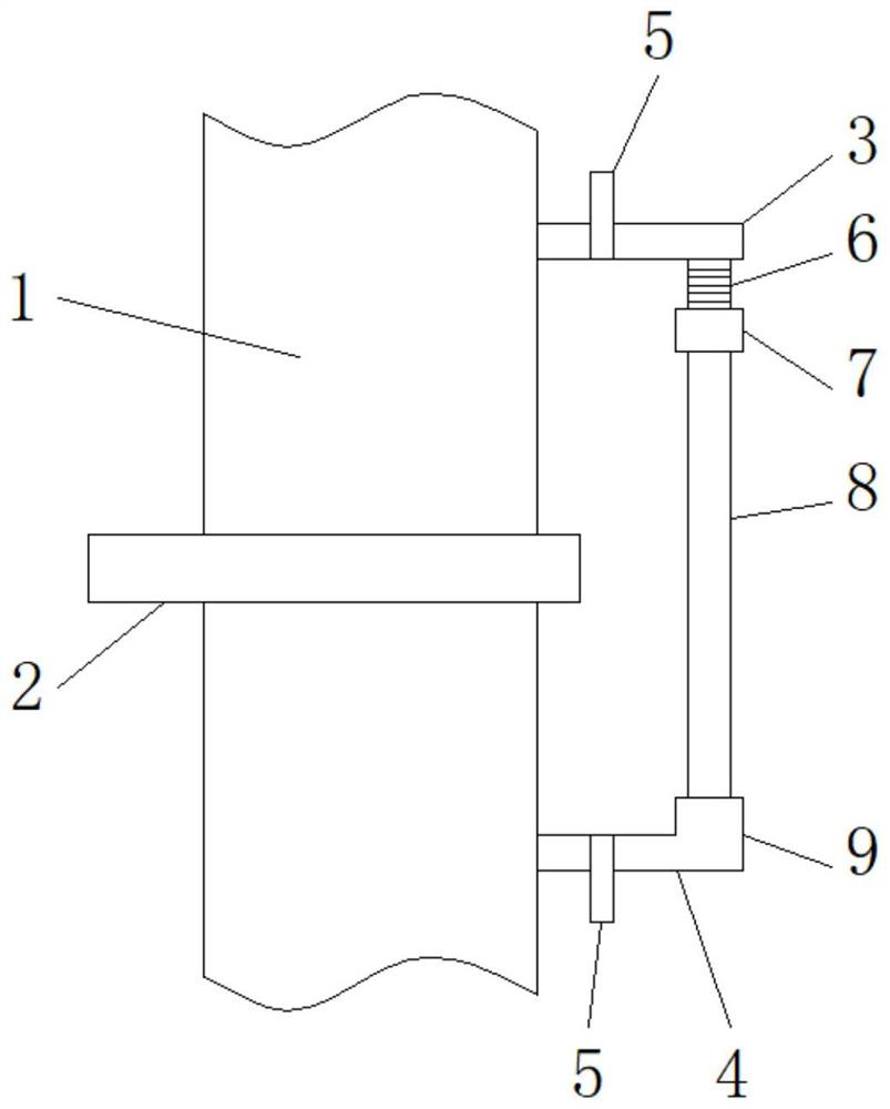
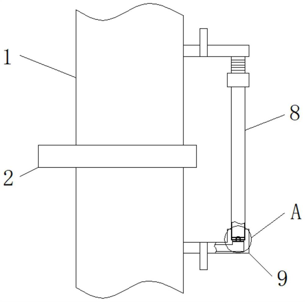
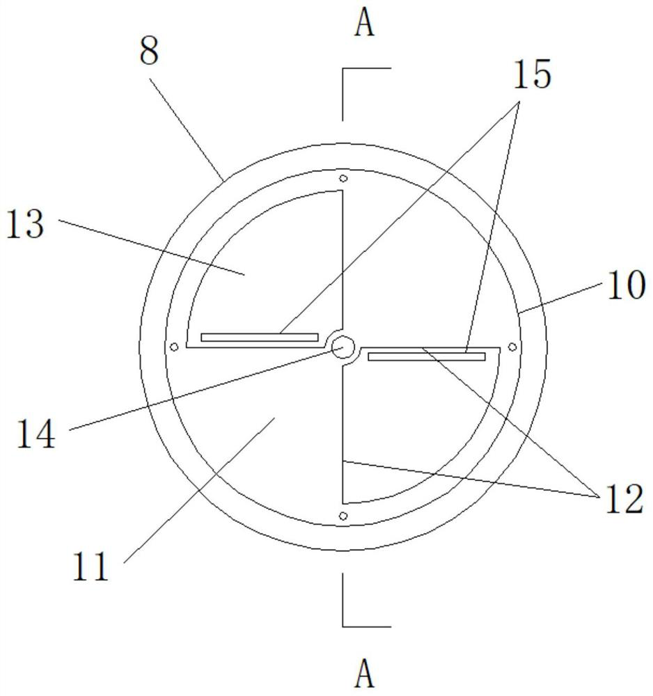
[0033] see Figure 1-11 , the present invention provides a technical solution: a linkage exhaust gas sampling structure for combustion exhaust gas detection, including an exhaust gas pipe 1, a main control valve 2, an upper shunt pipe 3, a lower shunt pipe 4, a sub-control valve 5, and a corrugated hose 6 , upper connecting sleeve 7, exhaust gas sampling pipe 8, lower connecting sleeve 9, fixing groove 10, fixing plate 11, air vent 12, sealing plate 13, connecting shaft 14, adjusting plate 15, connecting head 16, tension spring 17, sealing Cap 18, sealing ring 19, limit groove 20, support frame 21, push rod 22 and sealing gasket 23, the main control valve 2 is arranged on the waste gas pipe 1, and the waste gas pipe 1 above the main control valve 2 side is weld...


PUM


Abstract

The invention discloses a linkage type waste gas sampling structure for combustion waste gas detection, which comprises a waste gas pipe, a main control valve, a sub-control valve, a corrugated hose, a tension spring, a sealing cap, a sealing ring and a sealing gasket. A main control valve is installed, and an upper shunt pipe is welded on the exhaust pipe above one side of the main control valve, and a lower shunt pipe is welded on the exhaust pipe below the main control valve side, and both the upper shunt pipe and the lower shunt pipe are A sub-control valve is provided, the lower part of the outer end of the upper shunt pipe is threadedly connected with a corrugated hose, and the lower end of the corrugated hose is rotatably connected with an upper connecting sleeve, and the inner end of the upper connecting sleeve and the inner end of the lower connecting sleeve are respectively It is threadedly connected with the upper and lower ends of the exhaust gas sampling pipe. The linkage type exhaust gas sampling structure for combustion exhaust gas detection, through the improvement of both sides of the main control valve at the exhaust gas pipe, can realize the linkage opening and closing of the sealing plates at the openings at both ends of the exhaust gas sampling pipe, which is beneficial to the exhaust gas sampling of the exhaust gas sampling pipe. .

Description

technical field [0001] The invention relates to the technical field of combustion exhaust gas detection, in particular to a linkage type exhaust gas sampling structure for combustion exhaust gas detection. Background technique [0002] In some chemical industry or enterprises with waste gas emissions, most of the waste gas is produced by combustion or chemical reaction. If the waste gas burned in this way is directly discharged into the air, it will pollute the atmosphere and affect people's living environment. When living in After the nearby residents inhale too much exhaust gas, it will cause damage to their bodies and affect the health of nearby residents. At present, the treatment of exhaust gas is mainly to connect the exhaust gas to the exhaust gas device through the pipeline for filtering treatment, so that the exhaust gas can meet the emission requirements. After meeting the standard, it will be discharged through the pipeline. [0003] When treating exhaust gas, it...

Claims


Application Information

Patent Timeline
Patent Type & Authority Patents(China)
IPC IPC(8): G01N1/22
CPCG01N1/2247
Inventor 石卫祥
Owner 广西益全检测评价有限公司
Why Eureka
Try Eureka