
Methods and Arrangements to Detect a Failure in a Communication Network

a communication network and failure detection technology, applied in the field of communication networks, can solve the problems of reducing the efficiency of a communication system, unable to detect a subset of network adapters, and insufficiently meeting the growing demand of ethernet systems

Inactive Publication Date: 2007-11-01
IBM CORP
View PDF27 Cites 43 Cited by
  • Summary
  • Abstract
  • Description
  • Claims
  • Application Information

AI Technical Summary

Benefits of technology

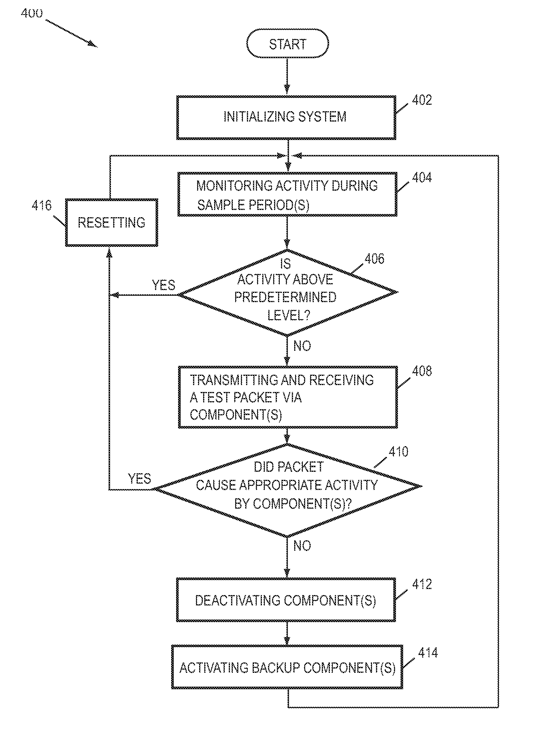
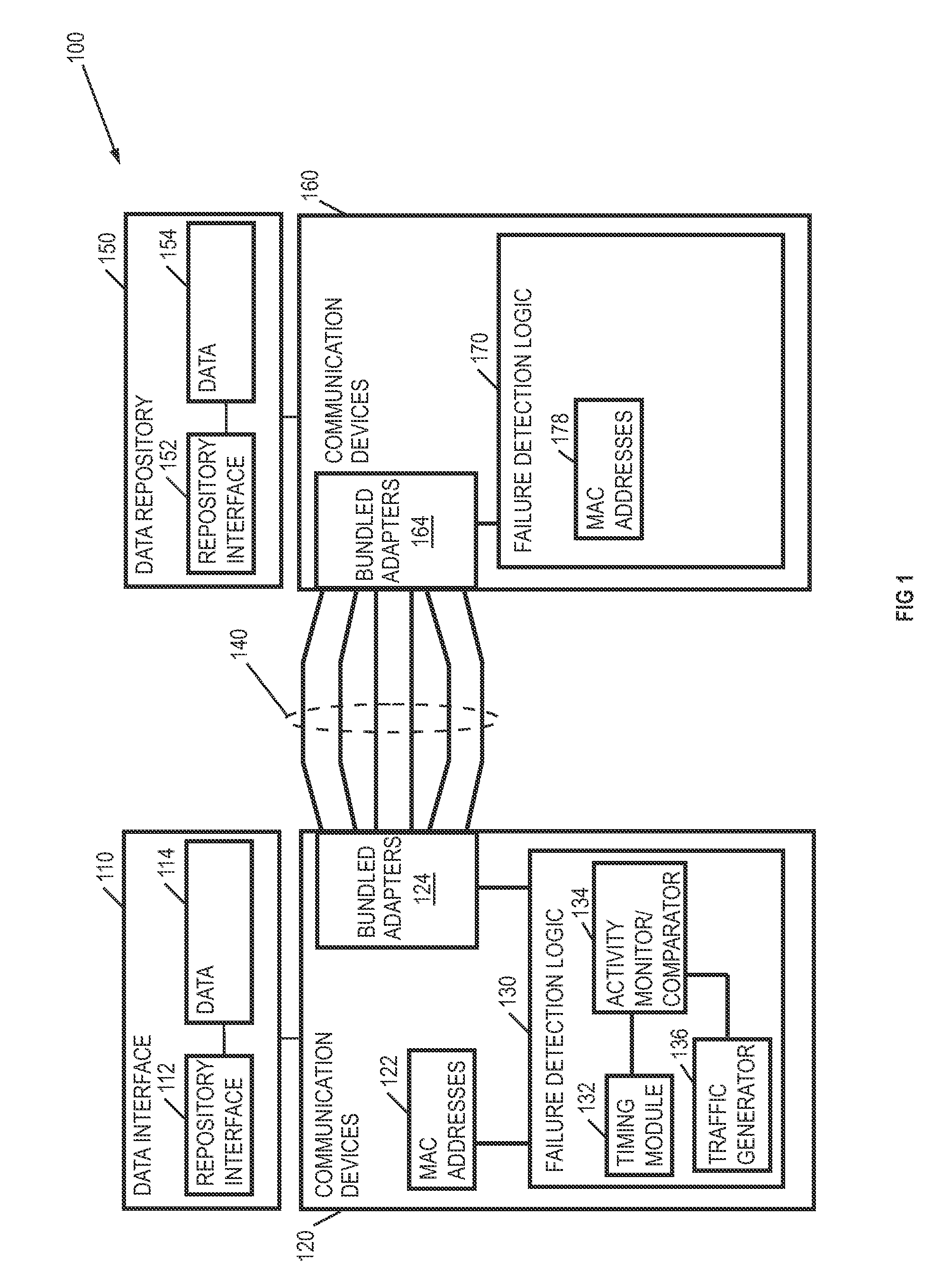
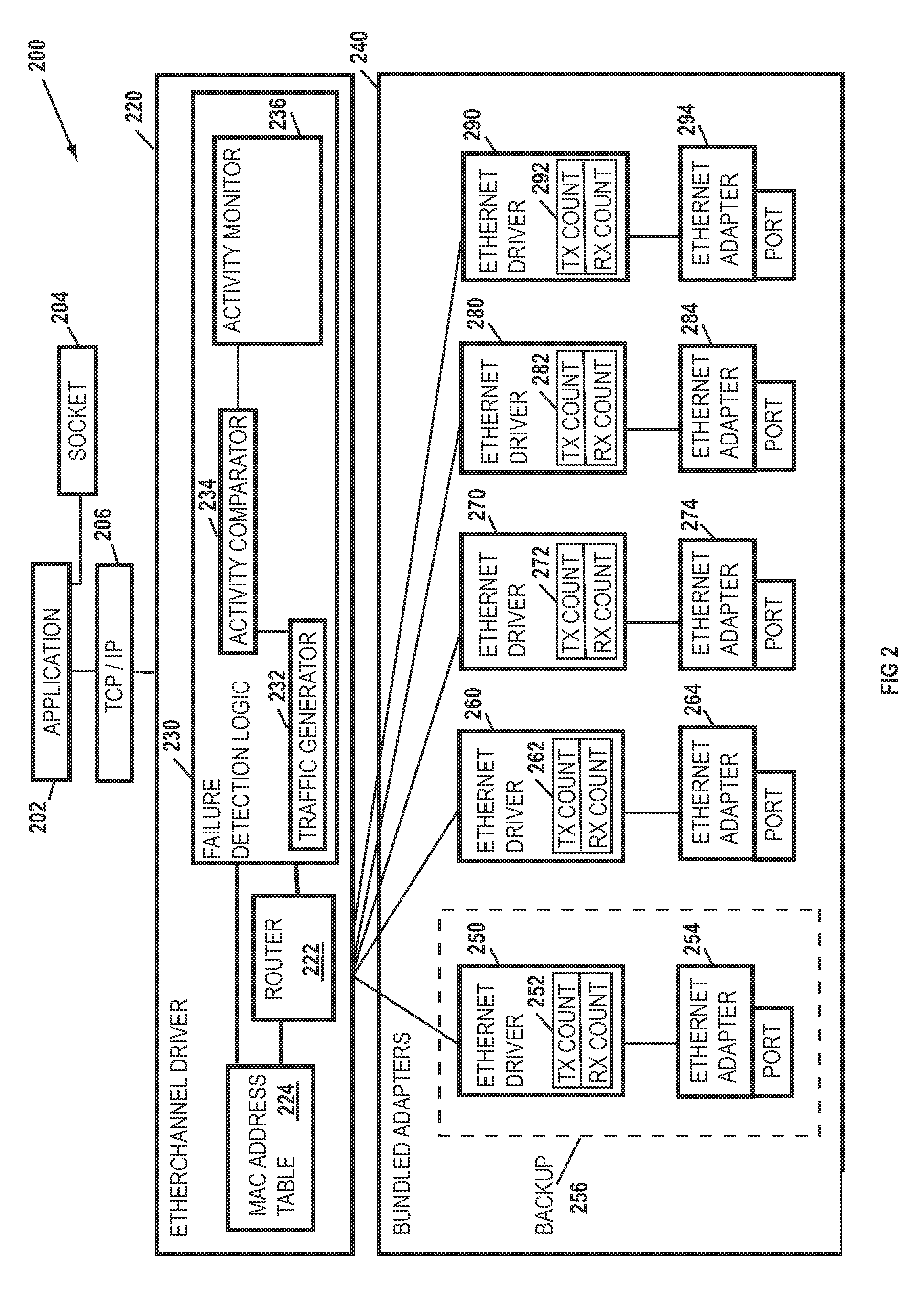
The patent describes methods and arrangements to detect failures in communication network interfaces with bundled components such as network adapters and sub-components. The methods involve routing data to a communication component that shares at least one Internet protocol address with other communication components of the bundle, monitoring the activity level of the communication component, and comparing it to a predetermined activity level to identify a failed component. The apparatus and system described in the patent make use of a traffic generator, an activity monitor, and an activity comparator to detect and flag failed components. The computer program product described in the patent includes a computer useable medium with a computer readable program that causes a computer to perform the methods described in the patent. The technical effects of the patent include improved detection and mitigation of failures in communication network interfaces, improved reliability and efficiency of network operations, and reduced downtime for maintenance and repair.

Problems solved by technology

However, even these Ethernet systems cannot adequately meet the growing demand.
A problem with current failure detection schemes is that they do not allow detection of a subset of the network adapters in a bundle of adapters.
The process of, retransmitting until a successful communication is achieved, greatly reduces the efficiency of a communication system.

Method used


Image

  • Methods and Arrangements to Detect a Failure in a Communication Network
  • Methods and Arrangements to Detect a Failure in a Communication Network
  • Methods and Arrangements to Detect a Failure in a Communication Network

Examples


Embodiment Construction

[0022] The following is a detailed description of novel embodiments depicted in the accompanying drawings. The embodiments are in such detail as to clearly communicate the subject matter. However, the amount of detail offered is not intended to limit anticipated variations of the described embodiments; but on the contrary, the claims and detailed description are to cover all modifications, equivalents, and alternatives falling within the spirit and scope of the present teachings as defined by the appended claims. The detailed descriptions below are designed to make such embodiments understandable to a person having ordinary skill in the art.

[0023] Generally, methods and arrangements to detect failures in communication networks having bundled components are provided herein. While specific embodiments will be described below with reference to adapters, components, circuits or logic configurations, those of skill in the art will realize that embodiments of the present disclosure may a...


PUM


Abstract

Methods and arrangements to monitor communication components such as a network adapters for activity, and identify components that have lower than normal levels of activity are provided. An identified communication component can become suspect component and a candidate for further testing, including different forms of interrogation. Process for interrogating candidates can include generating and sending test packets having the media access control (MAC) address of the candidate to the candidate and if activity is not detected subsequent to the interrogation, the candidate can be flagged as a failed component. Correspondingly, the component can be deactivated and removed from service. In a further embodiment, a backup component can be activated and assume the role previously held by the failed component.

Description

FIELD [0001] The present disclosure relates generally to communications networks. More particularly, the present disclosure relates to methods and arrangements for detecting failures of individual components in a bundle of communication components, such as bundled adapters. BACKGROUND [0002] The demand for speed and reliability in communications between communication devices such as servers, routers, switches and computers continues to increase. Applications or other programs that demand significant network resources, such as streaming on-line media continue to grow in popularity. Further, the number of users continues to increase and, as bandwidths increase, users invent new uses for the improved bandwidths. Thus, the demand for bandwidth in networks that are already operating near capacity appears to be ever increasing. [0003] Ethernet-based communication networks have gained popularity in the marketplace and variations of the Ethernet technologies continue to provide improved ban...

Claims


Application Information

Patent Timeline
Patent Type & Authority Applications(United States)
IPC IPC(8): G06F15/173
CPCH04L45/00Y02B60/33H04L45/28H04L45/245Y02D30/50
Inventor HUA, BINH K.KODUKULA, SIVARAMA K.
Owner IBM CORP
Learn More