Using 3-dimensional rendering effects to facilitate visualization of complex source code structures

Inactive Publication Date: 2007-11-01
SUN MICROSYSTEMS INC
View PDF6 Cites 46 Cited by
  • Summary
  • Abstract
  • Description
  • Claims
  • Application Information

AI Technical Summary

Benefits of technology

[0016] In a variation on this embodiment, the system facilitates displaying debugging tools within the 3D GUI, which involve

Problems solved by technology

Unfortunately, these existing tools have significant limitations in the way the query results are presented to the user.
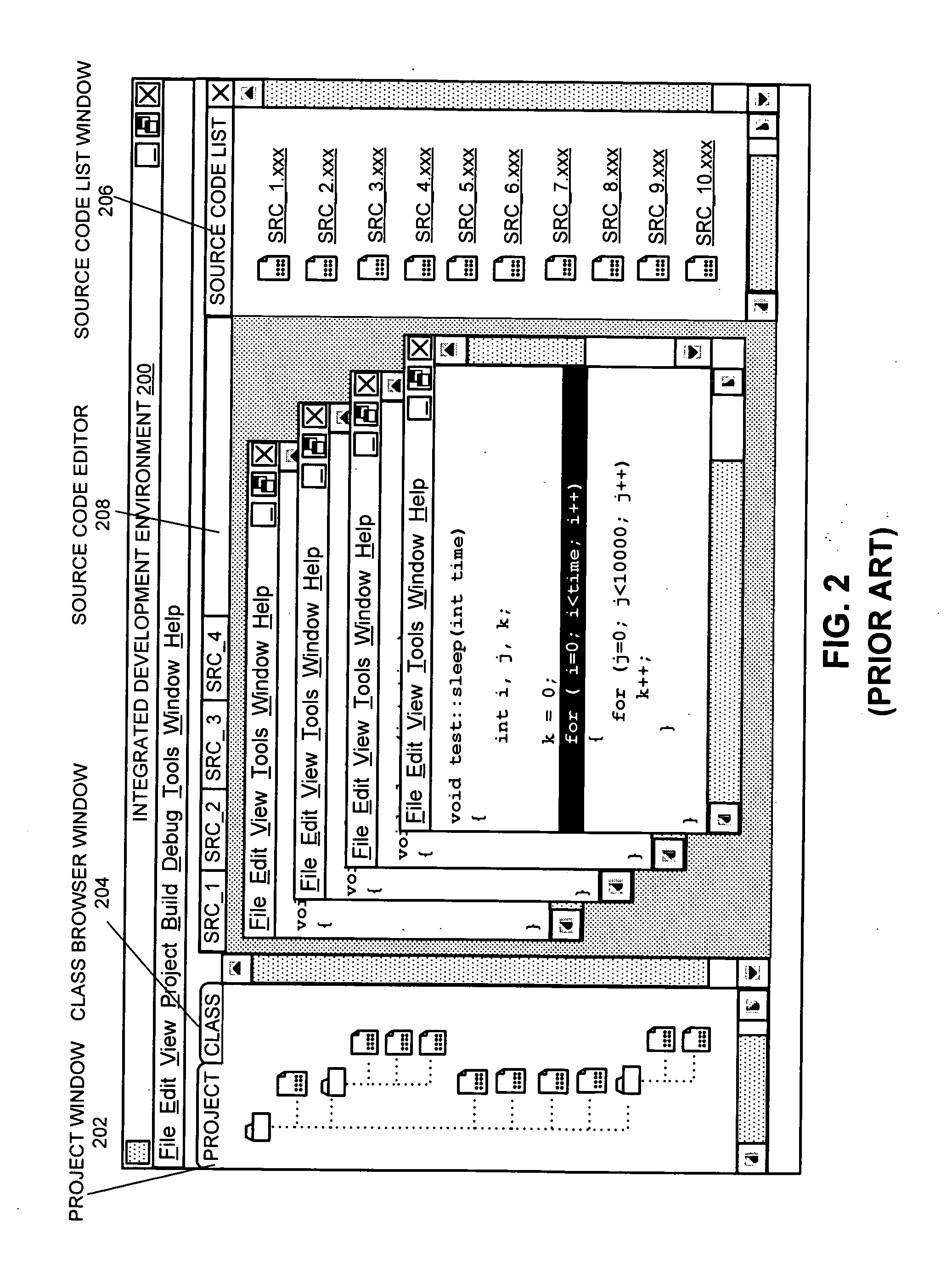
However, because of the 2D visual limitations of the UI, the display environment quickly becomes crowded when more than just a few editor windows are displayed within the IDE.
Another limitation of existing IDEs arises when displaying a call-graph associated with a list of source code files for a project, wherein the call-graph displays call relationships between methods in the source code files.
Unfortunately, when a standard 2D UI is used to display complex source code structures, the associated call

Method used


Image

  • Using 3-dimensional rendering effects to facilitate visualization of complex source code structures
  • Using 3-dimensional rendering effects to facilitate visualization of complex source code structures
  • Using 3-dimensional rendering effects to facilitate visualization of complex source code structures

Examples


Embodiment Construction

[0023] The following description is presented to enable any person skilled in the art to make and use the invention, and is provided in the context of a particular application and its requirements. Various modifications to the disclosed embodiments will be readily apparent to those skilled in the art, and the general principles defined herein may be applied to other embodiments and applications without departing from the spirit and scope of the present invention. Thus, the present invention is not limited to the embodiments shown, but is to be accorded the widest scope consistent with the claims.

[0024] The data structures and code described in this detailed description are typically stored on a computer-readable storage medium, which may be any device or medium that can store code and / or data for use by a computer system. This includes, but is not limited to, magnetic and optical storage devices such as disk drives, magnetic tape, CDs (compact discs), DVDs (digital versatile discs ...


PUM


Abstract

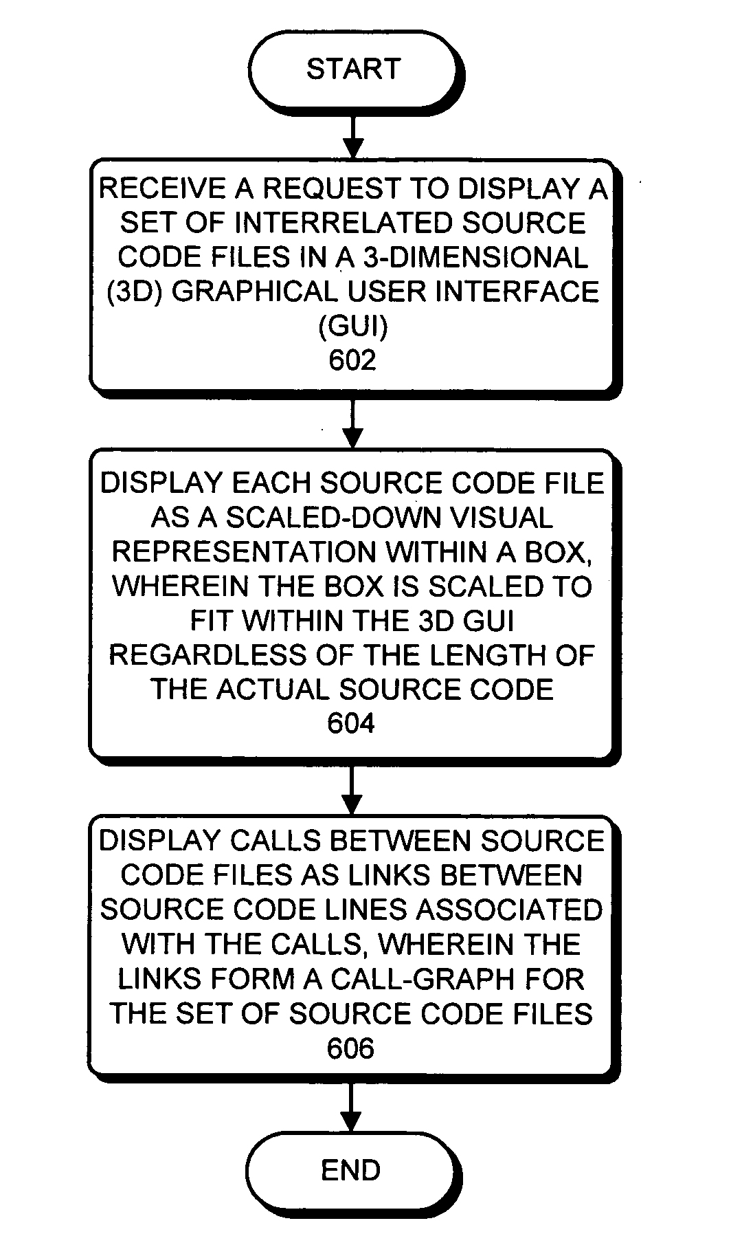
One embodiment of the present invention provides a system that uses three-dimensional (3D) rendering effects within a 3D graphical user interface (GUI) to enable a user to efficiently visualize and navigate through complex source code structures. During operation, the system receives a request to display a set of source code files in a 3D GUI. Next, in response to the request, the system displays each source code file as a scaled-down version of the actual source code within a box in the 3D GUI, wherein the box is scaled to fit within a viewing window of the 3D GUI regardless of the length of the source code in the file. Note that the scaled-down source code within the box preserves the structure of the actual source code file, including line lengths and indentations. The system also displays calls between source code files as links between source code lines associated with the calls, wherein the links form a call-graph between the set of source code files.

Description

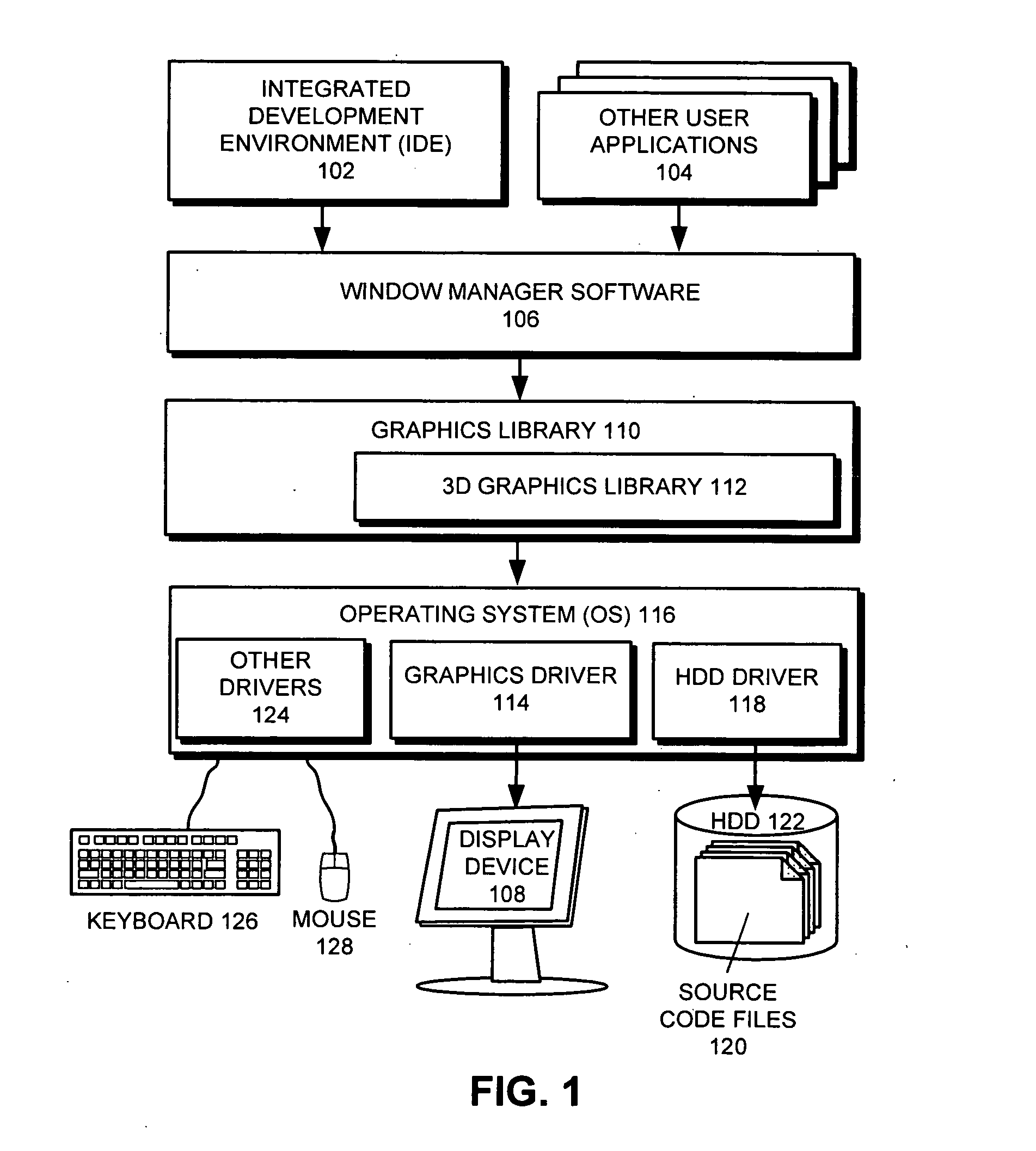
BACKGROUND [0001] 1. Field of the Invention [0002] The present invention relates to user-interfaces for computer systems. More specifically, the present invention relates to a method and an apparatus that uses advanced graphics rendering techniques to enable a user to efficiently visualize and navigate through complex source code structures. [0003] 2. Related Art [0004] Modern integrated development environments (IDEs) provide a user with a wide range of tools to explore a project's source code. In particular, some tools allow the user to perform queries to determine where a particular variable is used, and where a particular method is called from. Unfortunately, these existing tools have significant limitations in the way the query results are presented to the user. [0005] For example, consider a query for a method which is called from 10 locations spread across 8 source code files. In this case, an existing system typically displays two pieces of information which are useful to th...

Claims


Application Information

Patent Timeline
IPC IPC(8): G06F9/44
CPCG06F8/73
Inventor BYRNE, PAULKAWAHARA, HIDEYAHUNT, CHARLES J.
Owner SUN MICROSYSTEMS INC
Why Eureka
Try Eureka