
Energy absorbing member, method for producing same, and electromagnetic tube expansion method for rectangular cross-section member and polygon cross-section member

a technology of electromagnetic molding and energy absorbing parts, which is applied in the direction of bumpers, elastic dampers, vehicular safety arrangments, etc., can solve the problems of limiting the width of the flange formed by electromagnetic molding and the thinness of the flange, so as to reduce the degree of freedom in setting the location of bolt fastening, reduce the degree of buckling deformation, and reduce the effect of thickness

Active Publication Date: 2014-12-04
KOBE STEEL LTD
View PDF2 Cites 29 Cited by
  • Summary
  • Abstract
  • Description
  • Claims
  • Application Information

AI Technical Summary

Benefits of technology

The present invention relates to an energy absorbing member used in vehicles for absorbing energy during a collision. The invention provides a solution for molding a light-weighted energy absorbing member with good energy absorbing properties. The invention includes a metal molding material with an excessive line length, which allows for the formation of a flange with a large diameter. The metal molding material also has ridges parallel to the circumferential wall that suppress buckling deformation at collision. The invention also includes an aluminum alloy material with irregular regions that have an excessive line length, which prevents breakage and ensures a sufficient large electromagnetic molding force. The invention further includes a method for molding the energy absorbing member that suppresses a decrease in the thickness of the corners and deformation during crushing and deformation. The cross-sectional shape of the energy absorbing member is designed to coincide with the cross-sectional shape of the side member, ensuring stable deformation mode and predetermined energy absorbing performance.

Problems solved by technology

However, since the flange is expanded by tube expansion through electromagnetic molding, when the tube expansion rate (circumferential length after tube expansion / original circumferential length) is large, a crack may occur on the outer circumference of the flange, or the thickness may decrease, there is a limit in the width of the flange formed by electromagnetic molding.

Method used


Image

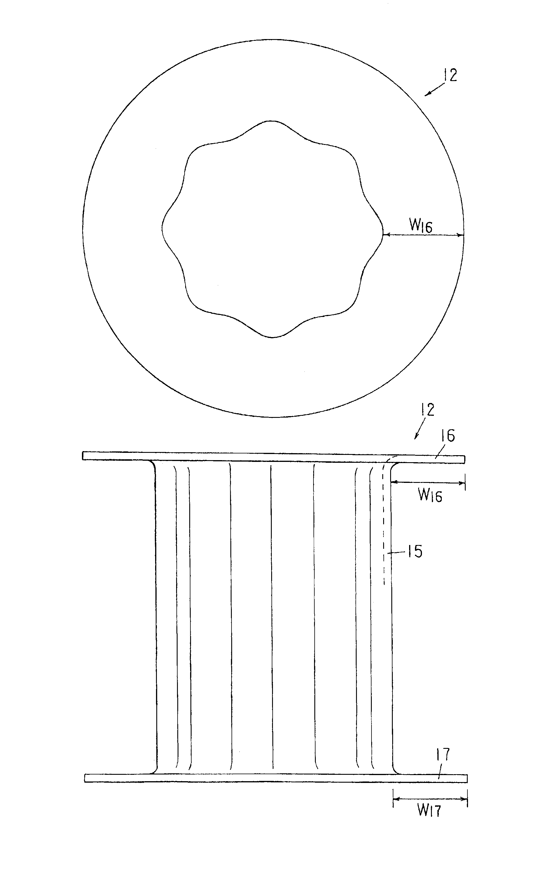
  • Energy absorbing member, method for producing same, and electromagnetic tube expansion method for rectangular cross-section member and polygon cross-section member
  • Energy absorbing member, method for producing same, and electromagnetic tube expansion method for rectangular cross-section member and polygon cross-section member
  • Energy absorbing member, method for producing same, and electromagnetic tube expansion method for rectangular cross-section member and polygon cross-section member

Examples


Embodiment Construction

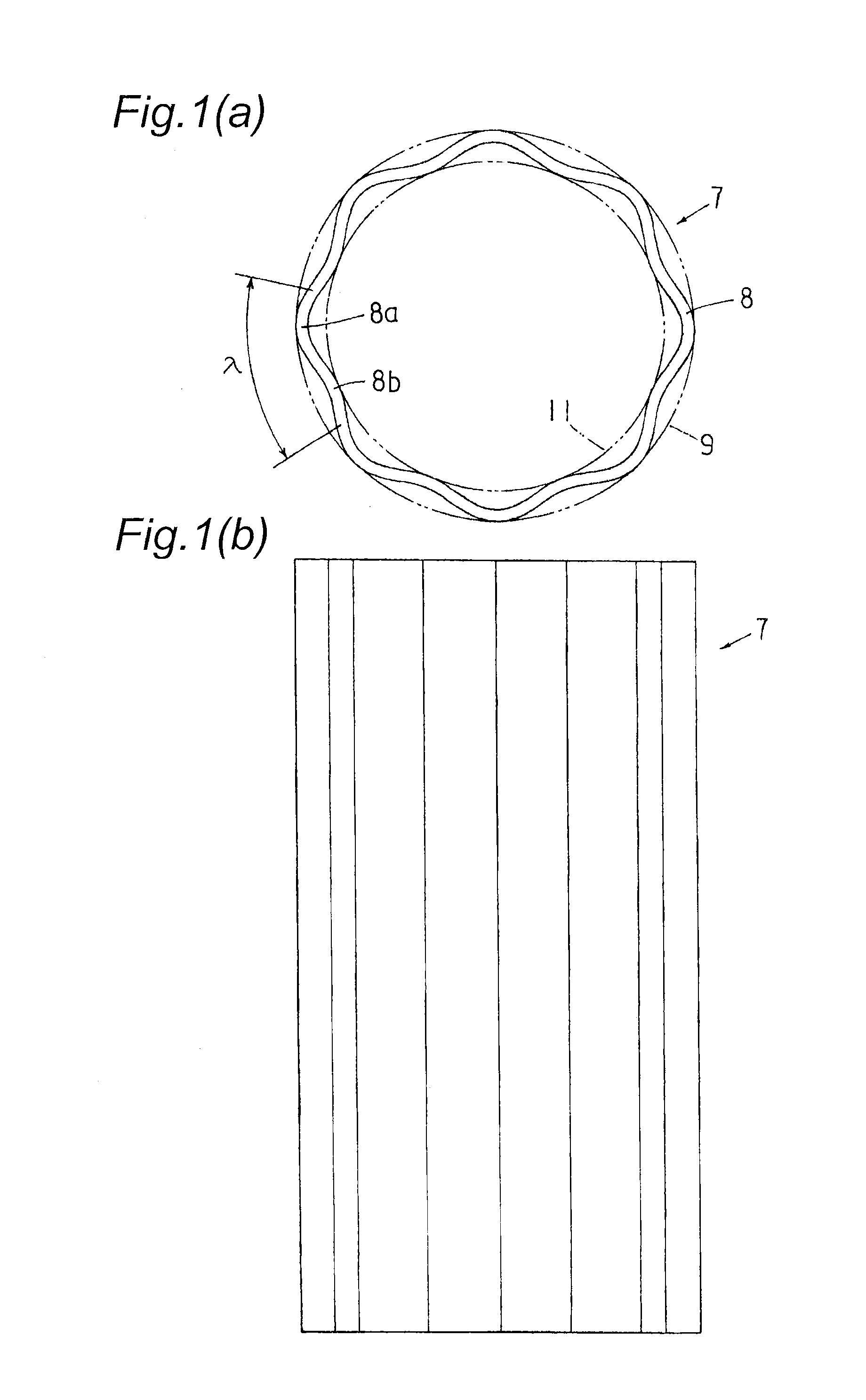
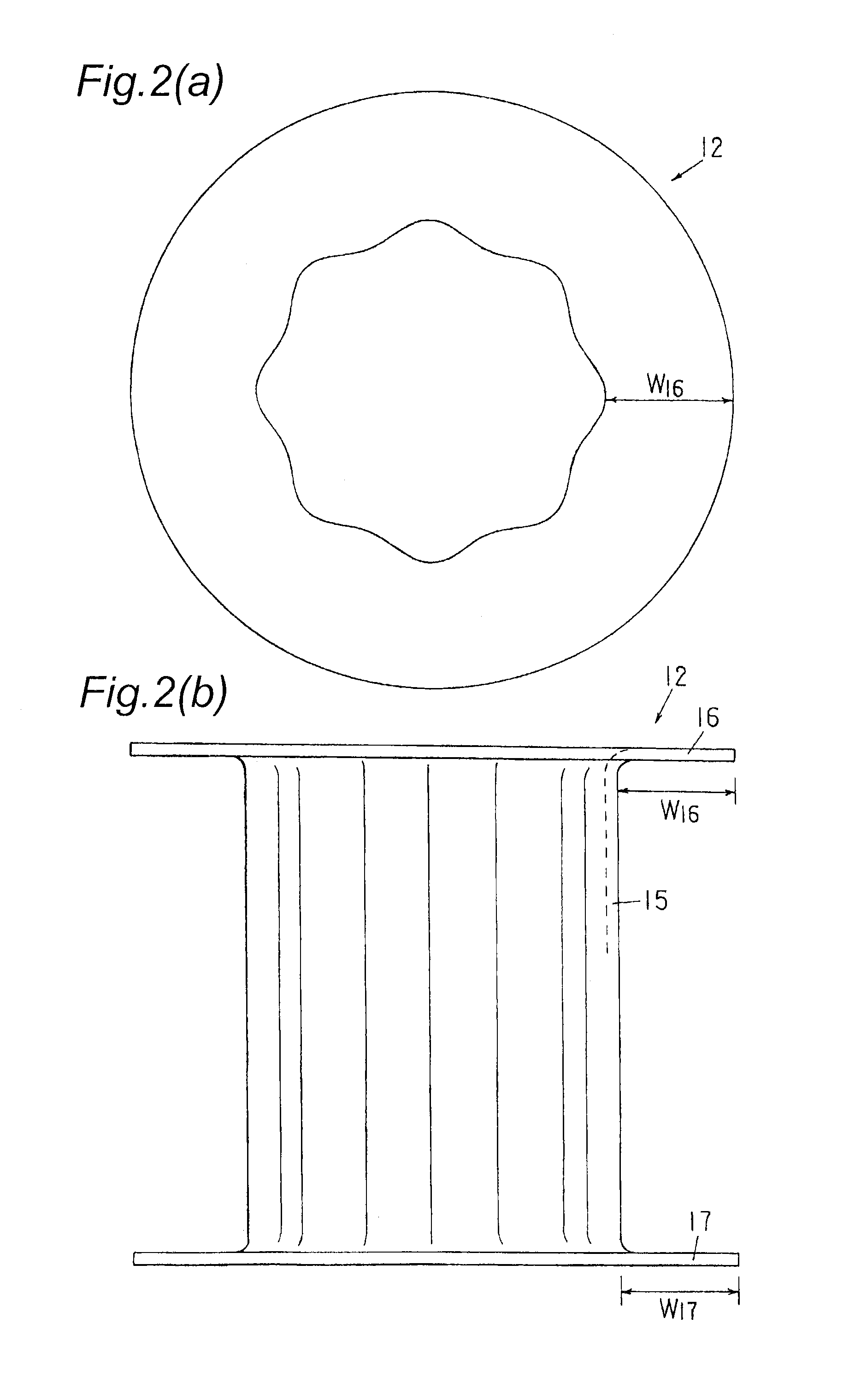
[0092]An energy absorbing member according to the present invention will be specifically described below using mainly a bumper stay as an example with reference to FIGS. 1 to 15. The description of the bumper stay is also applied to other energy absorbing members.

[0093]First, with reference to FIG. 14, a conventional metal molding material (stay material) and the energy absorbing member (bumper stay) will be described.

[0094]FIGS. 14(a) and 14(b) each show a stay material 1 acquired by cutting a metal molding material (aluminum alloy extruded material) by a predetermined length. The stay material 1 is a cylindrical body having a circular cross section, and in this example, both end faces (cut faces) are located within a plane vertical to the axial direction. The stay material 1 acquired by press-molding or roll-molding a metal plate into a tubular shape may be used.

[0095]For example, as described in Patent Documents 7 and 8, a circumferential wall 2 of the stay material 1 except its ...


PUM

PropertyMeasurementUnit
Lengthaaaaaaaaaa
Timeaaaaaaaaaa
Diameteraaaaaaaaaa

Abstract

An end of a stay material made of a tubular aluminum alloy extruded material is expanded by electromagnetic molding to form a flange for producing a bumper stay. The flange width is increased without cracking and a decrease in the thickness. A stay material having a circumferential wall undulating in a waveform pattern is used. A circumferential length L (one round length along waveform pattern) of the outer periphery wall along the circumferential direction of the stay material is longer than a circumferential length L0 of a simple cylindrical circumferential wall having the same outer diameter (circumscribed circle) (L>L0). L−L0 is an excessive line length. Since the circumferential wall has the excessive line length, when the end of the circumferential wall is expanded to form the flange, the flange having a large diameter can be formed.

Description

TECHNICAL FIELD[0001]The present invention relates to an energy absorbing member such as bumper stays for absorbing collision energy at collision of automobiles and a method for producing the energy absorbing member, as well as an electromagnetic tube expansion method for a rectangular cross-section member and a polygon cross-section member.BACKGROUND ART[0002]In recent years, standards on passenger car collision and pedestrian protection have been tightened, while improvement of the fuel efficiency and kinematic performances has been demanded. For example, a higher strength of bumper reinforces (bumper reinforcement), a higher energy absorbing efficiency and a lighter weight of bumper stays (crash box), and a higher energy absorbing efficiency of pedestrian protective components (see Patent Document 1) are in increasing demand. For trucks, to prevent a passenger car from underrunning, collision strength standards for front and rear underrun protectors (see Patent Document 2) are ti...

Claims


Application Information

Patent Timeline
IPC IPC(8): B60R19/34B21D53/88B21D26/14B21D19/12
CPCB60R19/34B21D26/14B21D53/88B21D19/12B21D39/044F16F7/12
Inventor ISHITOBI, HIDEKIHOSOI, HIROAKIAKASAKI, KEISUKE
Owner KOBE STEEL LTD
Learn More