Sheet Metal Web Stiffener And Chord Nailing Restrictor For Wooden I-Joist

a technology of sheet metal web and restrictor, which is applied in the direction of girders, joists, trusses, etc., can solve the problems of increasing the tendency of splicing, high mechanical strength, and the potential degrading factor of the load carrying capacity of the i-joist, so as to achieve the effect of increasing strength

Inactive Publication Date: 2007-11-08
DAVIS JOHN D
View PDF28 Cites 19 Cited by
  • Summary
  • Abstract
  • Description
  • Claims
  • Application Information

AI Technical Summary

Benefits of technology

[0010] Around the nail restricting hole may be a centering funnel for an easy centering of a suitable nail or the nail gun at the nail restricting hole. For increased strength at the bottom of the device and around the chord nailing access cavity, the chord plate may be angularly combined with a web plate that is parallel to and recessed from the web face. The chord nailing access cavity may also be open to a side lateral to the web face such that the nail restricting hole is additionally accessible along the I-joist front flush face.

Problems solved by technology

In addition to the small contact areas and the resulting large force concentrations, the nailing of the I-joist bottom chord introduces a splicing risk and consequently a potentially degrading factor on the load carrying capacity of the I-joist in the vicinity of the bearing rest.
The resulting high mechanical strength of the chord materials provides for small chord cross sections with an unfavorable side effect of increased splicing tendency compared to bulk lumber material otherwise used in architectural constructions.

Method used


Image

  • Sheet Metal Web Stiffener And Chord Nailing Restrictor For Wooden I-Joist
  • Sheet Metal Web Stiffener And Chord Nailing Restrictor For Wooden I-Joist
  • Sheet Metal Web Stiffener And Chord Nailing Restrictor For Wooden I-Joist

Examples


first embodiment

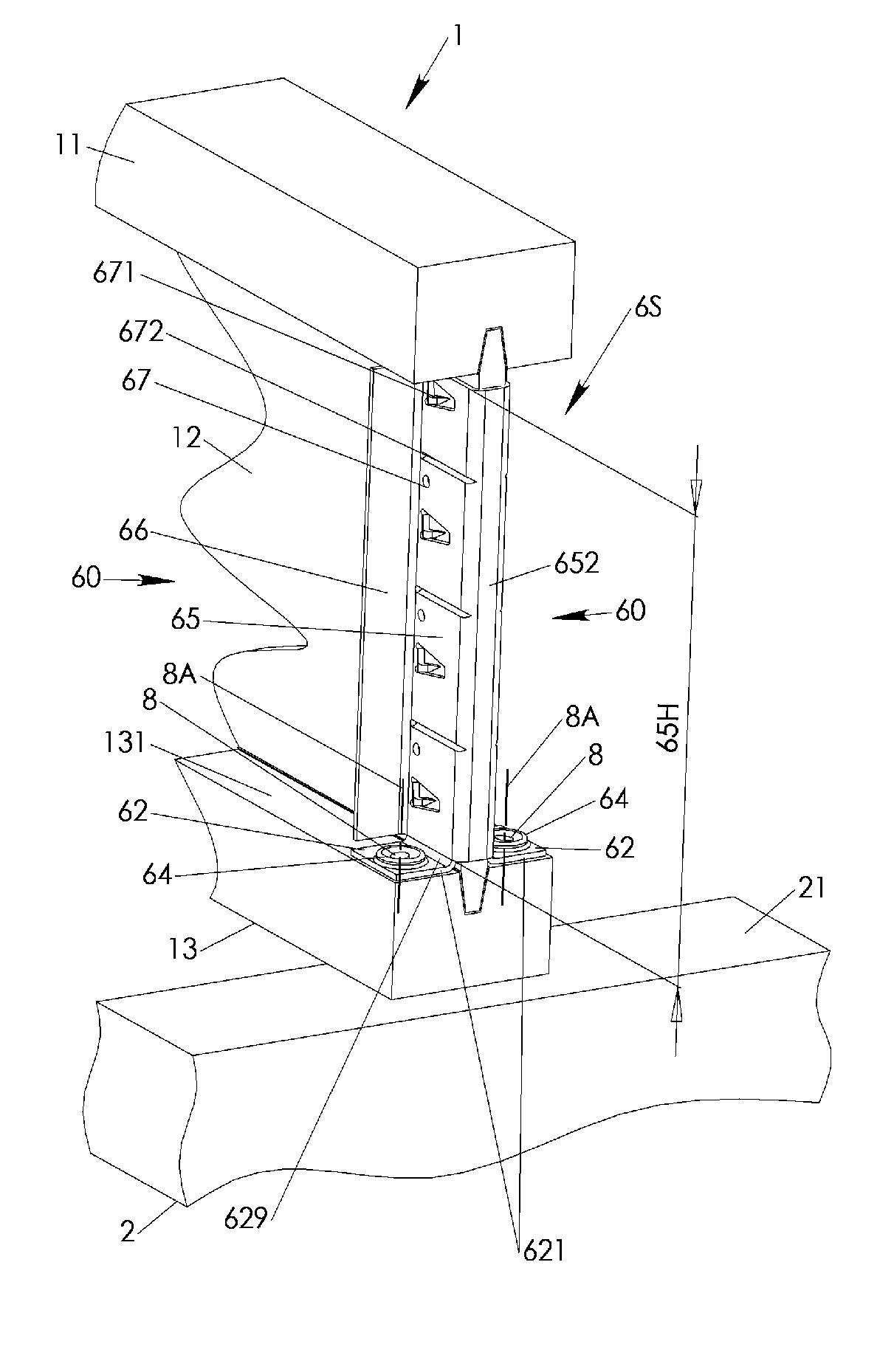
[0028] In the invention depicted in FIGS. 3, 4, AA, BB, 5, a device 6S for restricting nailing on a wooden I-joist 1 may feature a nail restricting hole 63 in a chord plate 62 that has a web edge 629. The nail restricting hole 63 is with its center axis 8A in a web nailing clearance CW to the web edge 629 and in a chord front clearance CF to a I-joist front flush face 621 / 6521. The nail restricting hole 63 may have a restricting diameter 63D such that only a suitable nail 8 having a shaft diameter 8D of up to the restricting diameter 63D may be nailed through the nail restricting hole 63. Web and chord nailing clearances CW, CF as well as restricting diameter 63D may be selected in accordance with well known chord nailing standards established by wooden I-joist 1 manufacturers. The chord plate 62 has a top 627 and bottom 628.

[0029] The I-joist front flush face 621 / 6521 is preferably perpendicular to the web edge 629. In case of an employed web front bridge plate 652 described in mor...

second embodiment

[0037] In the device 6N depicted in FIGS. 6, 7, two chord plates 62 are combined by an I-joist front plate 6222 extending substantially perpendicular away from the bottom side of the chord plates 62. Each of the two chord plates 62 has a chord front edge 6224 substantially collinear to each other and perpendicular to respective web edges 629. The web edges are facing each other substantially parallel spaced apart by web contacting gap 65G. Chord plates 62 and I-joist front plate 6222 may be fabricated from sheet metal, preferably as a monolithic structure. The device 6N operates mainly as nail restricting device. An independent well known web stiffener 5 may be attached after placement of the device 6N.

[0038] In the first and second embodiment device 6S, 6N a centering funnel 64 may be provided by the chord plate 62 surrounding the nail restricting hole 63. In case of the chord plate 62 being made of sheet metal, the centering funnel 64 may be embossed into the chord plate 62 with t...


PUM


Abstract

A monolithic sheet metal chord nailing restricting and web stiffening device features a chord plate combined with a web stiffening structure configured for lateral attachment to the web of a wooden I-joist. The chord plate is positioned on the bottom of the web stiffening structure and features a nail restricting hole having a diameter that corresponds to a predetermined diameter of a chord nail as defined by wooden I-joist manufacturers. The web stiffening structure has a web plate for attachment to the web and a buckling opposing web stiffening rib. Once the web stiffening structure is attached to the web above the bearing rest the nail restricting hole restricts chord nailing position and nail shaft diameter to manufacturer defined limits. Two devices may be combined by a web front bridge plate for simultaneous attachment of two opposite devices along an I-joist end.

Description

FIELD OF INVENTION [0001] The present invention relates to a chord nailing restricting web stiffener for a predetermined nailing restriction to a wooden I-joist chord at an I-joist bearing rest attachment location with simultaneous buckling opposing support at the I-joist bearing rest attachment location. BACKGROUND OF INVENTION [0002] In the field of architectural constructions, loads carried by wooden or wood like I-joists along their free spanning lengths are transferred onto bearing rests of relatively small areas. In addition to the small contact areas and the resulting large force concentrations, the nailing of the I-joist bottom chord introduces a splicing risk and consequently a potentially degrading factor on the load carrying capacity of the I-joist in the vicinity of the bearing rest. In response, I-joist manufacturers provide detailed nailing specifications on how to nail the I-joist's bottom chord onto the bearing rest in order to minimize the structurally degrading eff...

Claims


Application Information

Patent Timeline
Patent Type & Authority Applications(United States)
IPC IPC(8): E04C3/30
CPCE04B5/12E04C3/18E04C3/125
Inventor DAVIS, JOHN D.
Owner DAVIS JOHN D
Why Eureka
Try Eureka