Method for Producing a Coupling on a Pipe and Device for Producing Said Coupling

a technology of pipe and socket, which is applied in the field of making sockets on pipes, can solve the problems of saving significant material expenses, the fitting is exposed to the greatest stress, etc., and achieves the effects of increasing material expenses, increasing wall thickness inherently, and increasing wall thickness

Active Publication Date: 2007-11-08
FFG WERKE +1
View PDF8 Cites 8 Cited by
  • Summary
  • Abstract
  • Description
  • Claims
  • Application Information

AI Technical Summary

Benefits of technology

[0005] To avoid the discussed problems encountered in the method according to the prior art, the solution according to the invention provides, particularly together with the last expansion step, or in a separate working step, for an upsetting step at the pipe end, while predetermining the inner diameter with the expansion tool. The outer diameter is limited by the upsetting device and the outer shaping shoe which surrounds the pipe end during expansion.
[0006] The method according to the invention makes possible, particularly in case of pipes made of copper or alloys of Cu, Ni and Fe, to achieve an increase of the wall thickness at locations where its resistance to forces is needed for subsequent use. The increase of the wall thickness inherently depends from the stroke “X” shown in FIG. 2.
[0007] It has been found particularly advantageous to bring the wall thickness in the critical region to the same thickness as that of the initial material of the pipe. By virtue of such a feature of the invention, the wall thickness of the initial pipe portion may be less by the amount by which the wall thickness can be increased as a result of the upsetting step. In this manner significant expenses in material may be saved. In the apparatus according to the invention for making a socket on a pipe end with the described method, an expansion tool is axially introducible into the pipe end and has one or more conical and cylindrical parts determining the subsequent inner diameter of the pipe end. One or more shaping shoes having conical and cylindrical parts determine the subsequent outer diameter of the pipe end, and a substantially cylindrically structured upsetting device has a smallest inner diameter which corresponds, with the necessary play, to the maximum outer diameter of the expansion tool. The device has a substantially radially extending annular shoulder that may be pressed axially against the end face of the pipe end during the upsetting step.
[0008] Thus, by virtue of cooperation between the expansion tool, the shaping shoe and the upsetting device, a pipe socket of preferably multi-step enlargement may be formed. The upsetting device in essence comprises a cylindrical tube which has an inner annular recess for receiving the expanded pipe end and which is pressed axially against the end face of the pipe end. The inner diameters of the recess and the shaping shoe are provided preferably in the region in which an increase of the wall thickness needs to be effected and are coordinated with one another in such a manner that the desired wall thickness may be obtained dependent from the intended stroke, that is, dependent from a relative displacement between the upsetting device and the shaping shoe.
[0009] The invention will be described in an exemplary manner in more detail with reference to FIGS. 1 and 2.

Problems solved by technology

Then later, the fitting is exposed to the greatest stress at the location of the flange and in the region of the sealing elements; this, in the worst case, may lead to leakages.
In this manner significant expenses in material may be saved.

Method used


Image

  • Method for Producing a Coupling on a Pipe and Device for Producing Said Coupling
  • Method for Producing a Coupling on a Pipe and Device for Producing Said Coupling
  • Method for Producing a Coupling on a Pipe and Device for Producing Said Coupling

Examples


Embodiment Construction

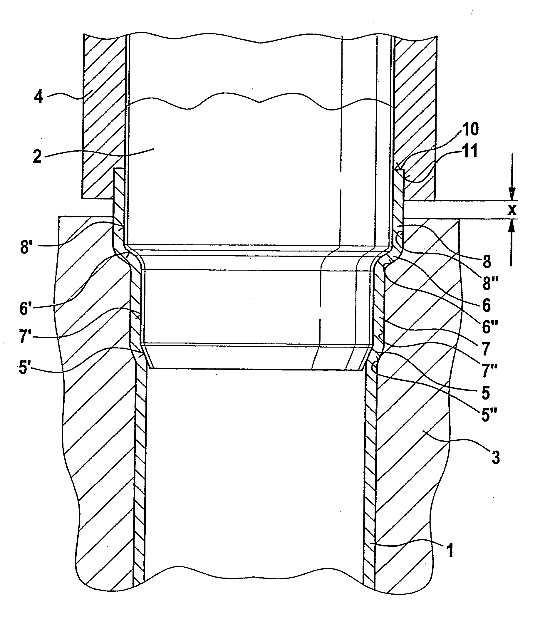
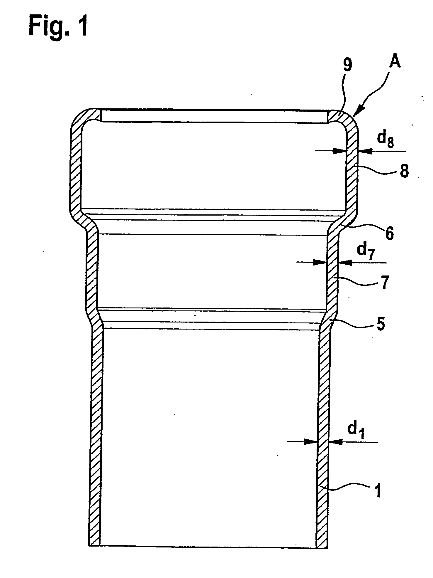
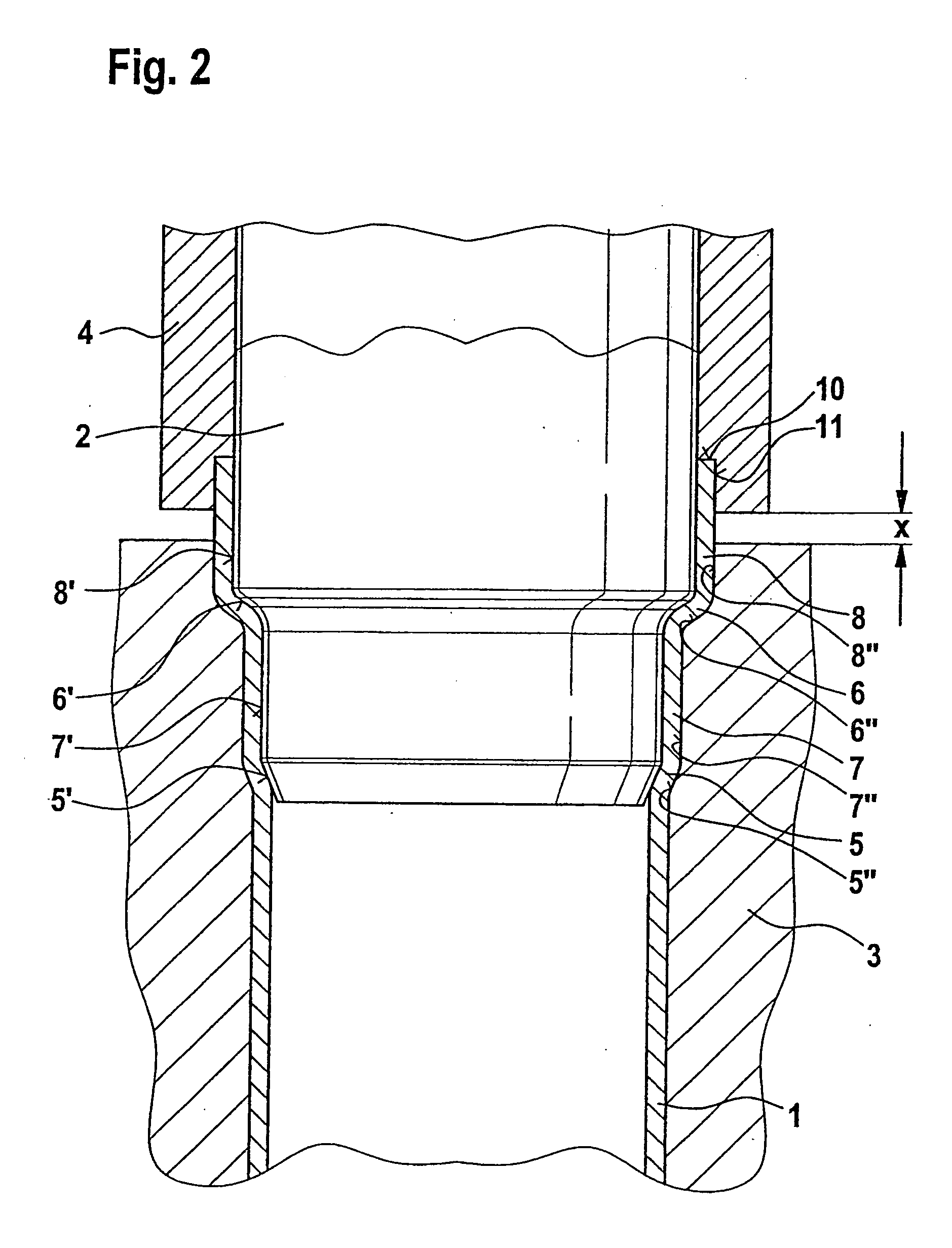
[0012] The finished pipe 1 shown in FIG. 1 has a wall thickness d1 which corresponds to the wall thickness of the original pipe material. Following a two-step expansion, the pipe has a first conical part 5, an adjoining first cylindrical part 7 having a wall thickness d7 which is reduced with respect to the wall thickness d1 in accordance with the extent of the expansion, a second conical part 6, an adjoining second cylindrical part 8 and an inwardly bent flange 9. The second cylindrical part 8 has a wall thickness d8 which, prior to providing the flange 9, was increased to the required extent by means of the upsetting step according to the invention. The wall thickness d8 should at least equal the wall thickness d7. It has even been found advantageous to bring the wall thickness up to the wall thickness d1.

[0013] In FIG. 2 the multi-step expansion tool 2 has already been axially pressed into the pipe end. The shape of the socket having parts 5 to 8 is formed on the inside by the p...


PUM

PropertyMeasurementUnit
thicknessaaaaaaaaaa
widthaaaaaaaaaa
widthaaaaaaaaaa

Abstract

In a method for producing a coupling on a pipe, preferably consisting of copper or steel or Cu-, Ni-, Fe-alloys, by way of a preferably graduated or one-stage expansion of the pipe end to create a much larger difference in diameter, an expansion tool is introduced axially into the end of the pipe. Once the expansion tool has been introduced into the pipe end, the region of the pipe end that is to be or has been expanded is completely or partially compressed, by a force acting axially on the pipe end, so that the external diameter of the pipe end that is to be processed is delimited by one or more shaping jaws that completely or partially surround the pipe end. The invention also relates to a device for producing a coupling on a pipe end according to the method.

Description

BACKGROUND AND SUMMARY OF THE INVENTION [0001] This invention relates to a method of making a socket on a pipe, preferably of copper or steel or alloys of Cu, Ni and Fe, by means of a preferably multi-step or single-step expansion of the pipe end with a large jump in diameter. For effecting the expansion, the pipe end is introduced axially into an expansion tool. The invention further relates to an apparatus for making a socket of such a type. [0002] In the manufacture of copper or steel fittings from pipes, the sockets at the pipe ends are made preferably by a stepped expansion of the pipe portion. In each required step the wall thickness is reduced during expansion of the pipe. It has been found, for example, that in case of a pipe having a nominal width >50 mm and a wall thickness of 2.7 mm, after a two-step expansion the wall thickness is only 2.4 mm. In the last step of the expansion where the thinnest wall thickness occurs, the pipe end is, as a rule, inwardly flanged to en...

Claims


Application Information

Patent Timeline
Patent Type & Authority Applications(United States)
IPC IPC(8): B21D11/08B21D41/02
CPCB21D41/02
Inventor VIEGNER, WALTER JR.BAUER, WALTER
Owner FFG WERKE
Why Eureka
Try Eureka