Tire Hil Simulator

a technology of vehicle models and simulators, applied in the field of tires hil, can solve the problem that the camber angle generated by the vehicle model when it is three-dimensionally considered cannot be reproduced in a testing apparatus

Inactive Publication Date: 2007-11-08
KOBE STEEL LTD +1
View PDF10 Cites 30 Cited by
  • Summary
  • Abstract
  • Description
  • Claims
  • Application Information

AI Technical Summary

Benefits of technology

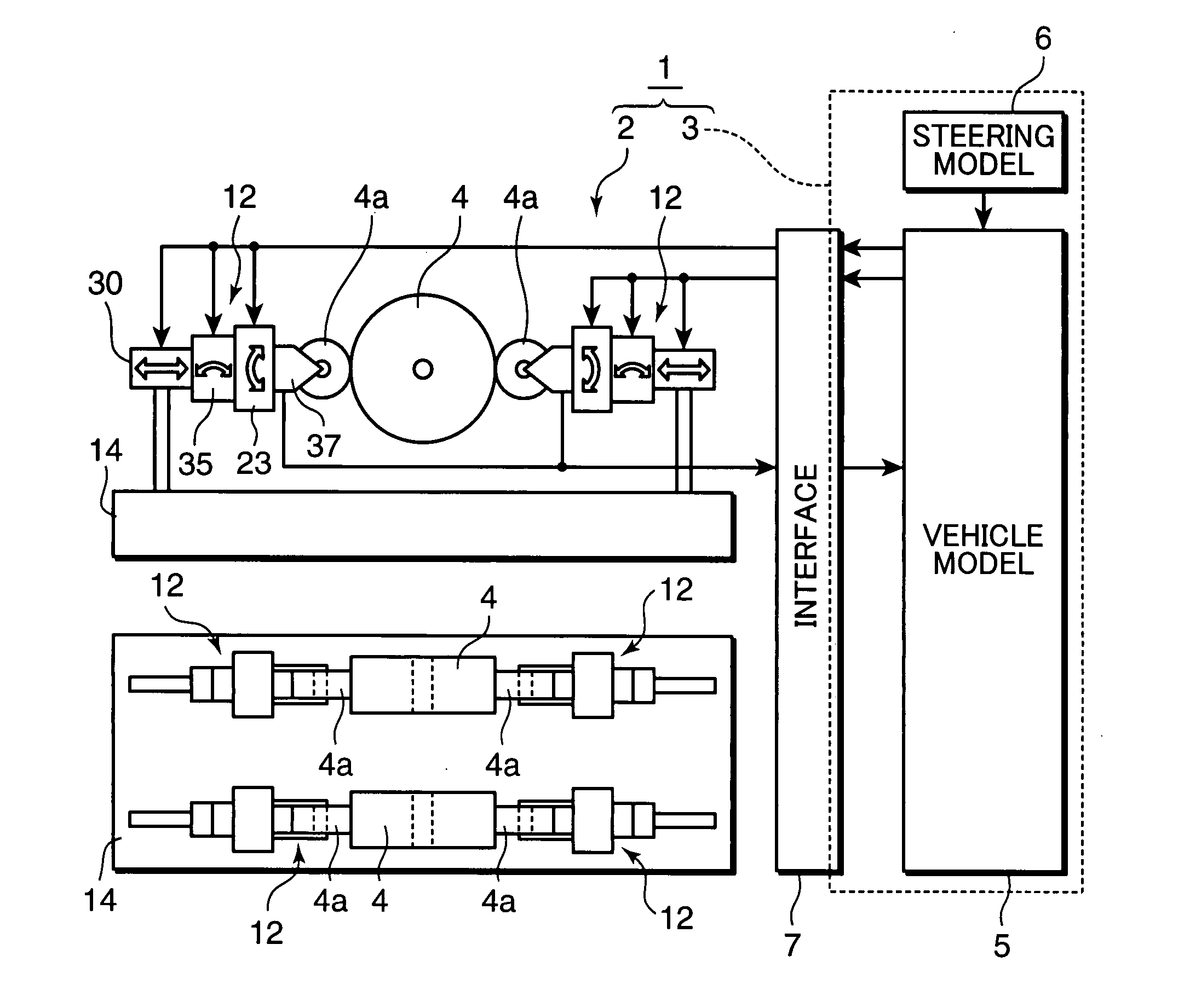
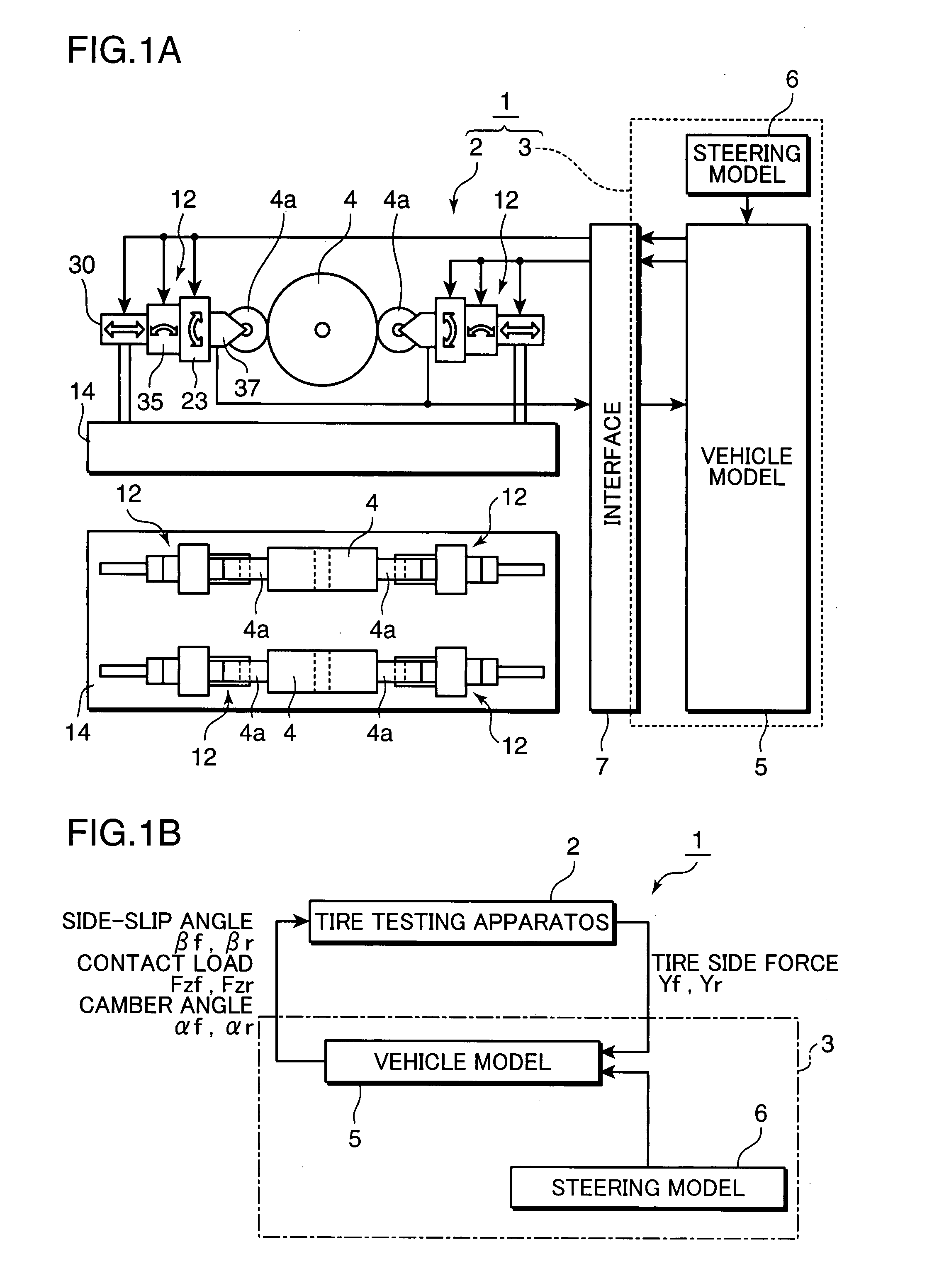
[0017] According to the present invention, performance characteristics of a real tire attached to the tire testing apparatus can be measured. Measurement data (i.e., the tire side force) and a steering angle are inputted in the vehicle model as an input value to thereby calculate, using the vehicle model, motion characteristics (i.e., contact load, side-slip angle and camber angle) of a vehicle in real time. Values obtained in this calculation are outputted as command values to actuators of the tire testing apparatus to thereby operate these actuators. In this way, the supporting state of the tire on the mimic

Problems solved by technology

This raises a disadvantage that a tire's camber angle based on a rolling angle of the vehicle generate

Method used


Image

  • Tire Hil Simulator
  • Tire Hil Simulator
  • Tire Hil Simulator

Examples


second embodiment

[0083]FIG. 8 and FIG. 9 show the present invention. In this embodiment, as shown in FIG. 8, each tire attachment portion 12 described above is provided with a braking force actuator 38. This braking force actuator 38 is adapted for imparting a braking force to the tire 4a, and is connected to each tire 4a at a position near the side-force measuring device 37. As shown in FIG. 9, each tire attachment portion 12 is connected via the interface 7 to the vehicle model 5.

[0084] In this embodiment, braking forces to the front wheels and the rear wheels which are derived from the vehicle model 5 are inputted as command values in the braking force actuator 38 to thereby give the braking force derived from the vehicle model 5 to each tire 4a. Consequently, the vehicle model 5 is imparted with a rotational motion in the pitching direction, thus enabling to generate a simulation in which a braking force is given.

third embodiment

[0085] the present invention is shown in FIG. 10 and FIG. 11. In this embodiment, as shown in FIG. 10, a drive unit 15 is provided with a speed detector 40 for detecting a speed at which the mimic road surface body 4 is driven. This speed detector 40 and the drive unit 15 are connected, as shown in FIG. 11, via the interface 7 to the vehicle model 5.

[0086] In this embodiment, since there is provided the means for measuring and controlling the drive speed of the mimic road surface body 4 (in the figure's example, the rotational speed of the drum which constitutes the mimic road surface body 4), the drive speed derived from the vehicle model 5 can be given to the mimic road surface body 4. This enables to generate a simulation in which the drive speed of the mimic road surface body 4 is changed.

fourth embodiment

[0087] the present invention is shown in FIG. 12 and FIG. 13. In this embodiment, as shown in FIG. 12, each drive unit 15 is provided with a driving torque detector 41 for detecting a torque by which the mimic road surface body 4 is driven. In this embodiment, a motor capable of controlling the rotational speed of the drum of the mimic road surface body 4 serves as the driving torque detector 41. As shown in FIG. 13, the driving torque detector 41 is connected via the interface 7 to the vehicle model 5. The vehicle model 5 has, as one of parameters, a rolling resistance which is derived based on a driving torque detection value outputted from the driving torque detector 41.

[0088] In this embodiment, a rolling resistance force is calculated based on the drum driving torque detected by the driving torque detector (or the motor) 41. This rolling resistance force is inputted in the vehicle model 5, thus enabling to generate a simulation in consideration of the effect of the rolling resi...


PUM


Abstract

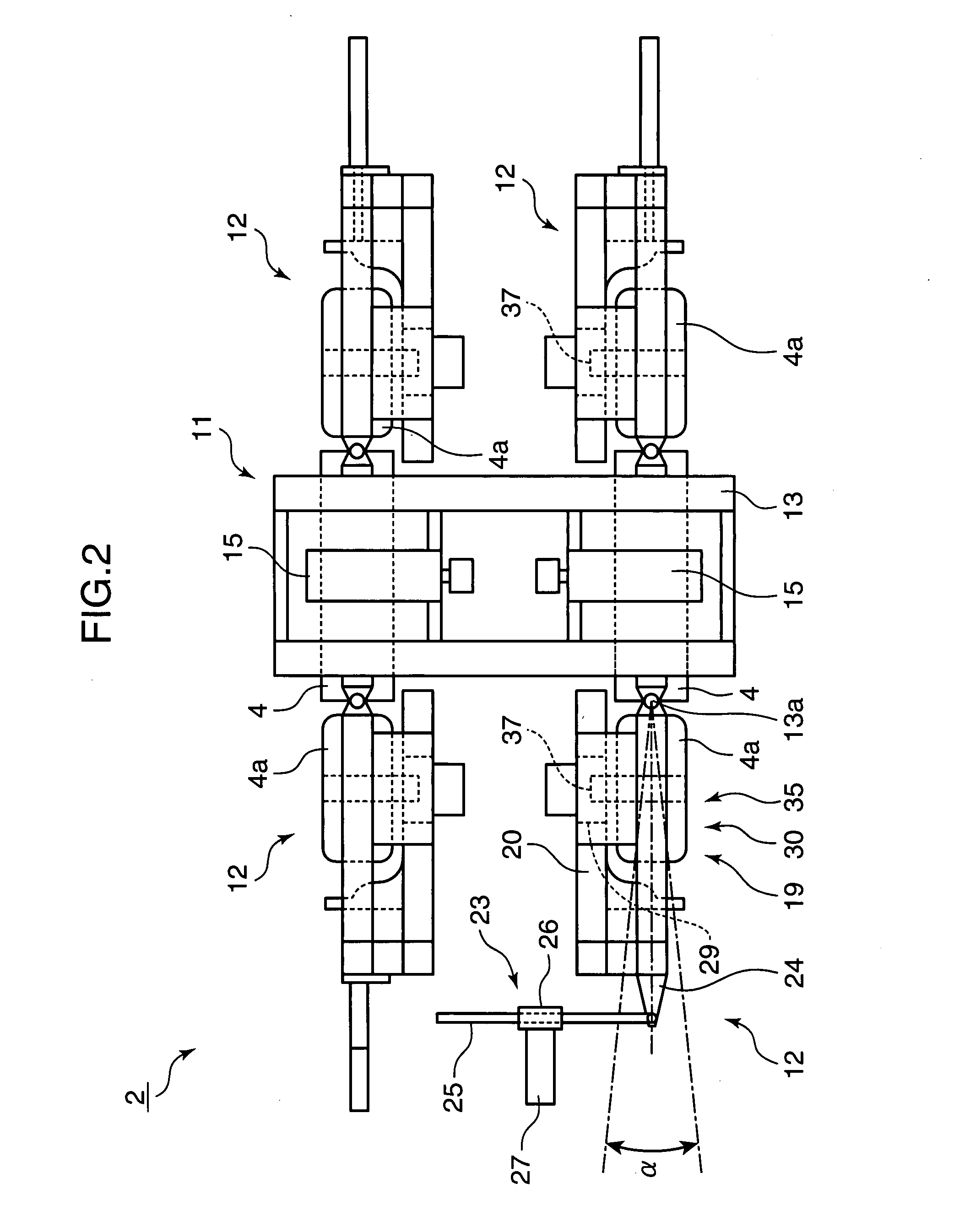
A tire HIL simulator is provided which is capable of, in a testing apparatus where a vehicle model is incorporated into a tire testing apparatus, reproducing the behavior of a tire which corresponds to the three-dimensional behavior of a vehicle, even if a three-dimensional vehicle model is used. As a device for resolving this, this tire HIL simulator includes a tire testing apparatus 2 and a controller 3 connected mutually. The tire testing apparatus 2 conducts a running test on a tire 4a using a mimic road surface body 4, and includes a side force measuring device 37 for measuring a tire side force and each actuator which gives a contact load, a side-slip angle and a camber angle, respectively. The controller 3 sets a steering angle and a tire side force from the side force measuring device 37 as an input value and calculates the three-dimensional motion of a vehicle using a vehicle model 5, and based on this calculation result, outputs each command value for the contact load, the side-slip angle and the camber angle to each actuator of the tire testing apparatus 2.

Description

TECHNICAL FIELD [0001] The present invention relates to a tire HIL (or Hardware-In-the-Loop) simulator which is capable of conducting a test under conditions close to real running test conditions for a vehicle. BACKGROUND ART [0002] In development of an automobile or the like case, optimizing a tire suspension system needs to be taken into account. In this case, a large number of conditions must be set, such as a tire's surface temperature, internal pressure and contact load, and further, the tire's material and shape. It takes a great deal of test time to set their optimum conditions. Besides, the effect of the mechanism or compliance of a suspension on a tire's performance needs to be examined. Therefore, in a computerized simulation, a complicated tire model is difficult to be used as it is when considering the optimization. On the other hand, in the case of a real running test, actual tire characteristics can be directly obtained, but it is difficult to reproduce a road surface ...

Claims


Application Information

Patent Timeline
IPC IPC(8): G01M17/02
CPCG01M17/022
Inventor IMANISHI, ETSUJIROHONKE, KOICHITSUTSUI, AKIRASUGANO, NAOKINANJO, TAKAOSUDA, YOSHIHIRO
Owner KOBE STEEL LTD
Why Eureka
Try Eureka