Submersible electrical power generating plant

a technology of submerged electrical power and generating plant, which is applied in the direction of electric generator control, machines/engines, mechanical equipment, etc., can solve the problems of devastating impact, few are aware of the seriousness of the problem, and operate at quite the same high capacity factor in that current, and achieve the effect of reducing the risk of accidents

Inactive Publication Date: 2007-11-08
ROBSON JOHN H
View PDF63 Cites 58 Cited by
  • Summary
  • Abstract
  • Description
  • Claims
  • Application Information

AI Technical Summary

Benefits of technology

[0036] The submersible electrical power generating structure, made of carbon fiber composites and other non-corroding plastics, has a superior located center of buoyancy (the center of gravity of that water being displaced), an inferior located center of gravity and a center of drag (that point where sum of all the drag forces caused by every exposed part of an object moving through a fluid are balanced). The power generating structure has a streamlined torpedo-shaped buoyancy tank with a nose end, a rear end, a top side, a bottom side, a left side, a right side, a plurality of valves and a plurality of compartments. The center of gravity of the submersible electrical power generating structure can be changed by adding water into or subtracting water from the plurality of compartments of the streamlined torpedo-shaped buoyancy tank. The streamlined torpedo-shaped buoyancy tank has a vertical tail fin capable of improving directional stability of the submersible electrical power generating structure. The vertical tail fin can be on either the top side of the submersible electrical power generating structure extending upward or the bottom side of the submersible electrical power generating structure extending downward. The water level in each of the plurality of compartments is adjustable by piping the water in and out through the plurality of valves.
[0047] Another option is to replace the conventional valves that drain the individual compartments with special check valves similar to the special check valves in the ballast water transfer system and have an electrically controlled valve in the common drain line. Because the special check valves prevent siphoning between the compartments, the only electrically controllable valve required would be in the common drain line.

Problems solved by technology

Perhaps the most frightening aspect about the approaching energy crisis is that so few are aware of the seriousness of the problem and the devastating impact that the worsening shortages of oil and natural gas will have upon our industrialized society, upon our nation, and upon our lives.
Although turbines designed for the Gulf Stream can also generate low-cost electricity from the Kuroshio, they would probably not operate at quite the same high capacity factors in that current as they would in the Gulf Stream.
Tidal currents are of interest—not because a tethered submersible power generator would be well suited for harvesting their kinetic energy—but because they also involve the generation of electricity underwater, the transmission of that power to shore, and because serious money is being invested in their development, even though their capacity factors are very low.
A wind turbine with many blades or very wide blades (turbines with a solid rotor) would be subject to extremely large forces when the wind blows at hurricane velocities because the energy increases with the cube of its velocity.
Although the amount of heat from all the losses in large generators is only about one percent of the output, it can be numerically great.
However, because plastics do not have the same ability to transfer heat as do the metal housings used on the wind turbines, and because there will be no outside source of air for cooling, some type of external cooling system will be required to dissipate the heat produced by the generators and gearboxes.
The problem with mounting the generating devices on platforms is that the strongest currents are located near the surface where the depths are usually greater than 1,200 feet and mounting the generating devices high above the ocean floor on giant structures would be extremely costly.
If the structures had shorter towers, the submersible power plants would be much more difficult to install and service and the turbines would be beneath the stronger current flow.
The problem with suspending the turbines from barges or pontoons is that they would interfere with ship traffic, be vulnerable to violent storms, and be unsightly.
Also the lifting force provided by the hydrofoil that joins the nacelles is at the same level as the heavy elements, further adding to a lack of stability.
Because the anchor lines attach directly ahead of the center of drag, the canted wing tips would have little effect on stability.
With the attachment point located at the center of buoyancy, if the device should have positive buoyancy, the canted wing tips would decrease stability.
With the anchor attachment points being behind this “stabilizing fin,” the fin would make the device more unstable.
A problem with this approach is that, although the purpose of the generator is to capture kinetic energy to maximize power output, it controls the depth by reducing that output.
Although these are counter-rotating turbines are side-by-side, because they are mounted on vertical shafts, their counter rotation has no effect on the device's stability.
In this and all other devices that use turbines mounted on vertical shafts—not only are the areas for capturing the energy of the moving fluid small in proportion to the frontal area of the device, they waste additional energy because—even though the fins on the reverse side of the vertical turbine may fold or open to allow water to have much less resistance as they rotate toward the front of the turbine—they still produce some drag that must be subtracted from the power produced by that side of the turbine that is being pushed by the kinetic energy of the flowing water.
The inefficiencies of all these vertical shafted turbines can be compared to using paddle wheels for propelling boats rather than modern propellers, except they would be worse because the top blades of a boat's paddle wheel meets far less resistance when moving forward through the air than would those blades of a vertical-shafted water turbine blades moving against the much denser water.
Shrouds and Venturi-shaped tubes are not used on commercial wind-powered turbines because they do not increase the velocities enough to justify their cost.

Method used


Image

  • Submersible electrical power generating plant
  • Submersible electrical power generating plant
  • Submersible electrical power generating plant

Examples


Embodiment Construction

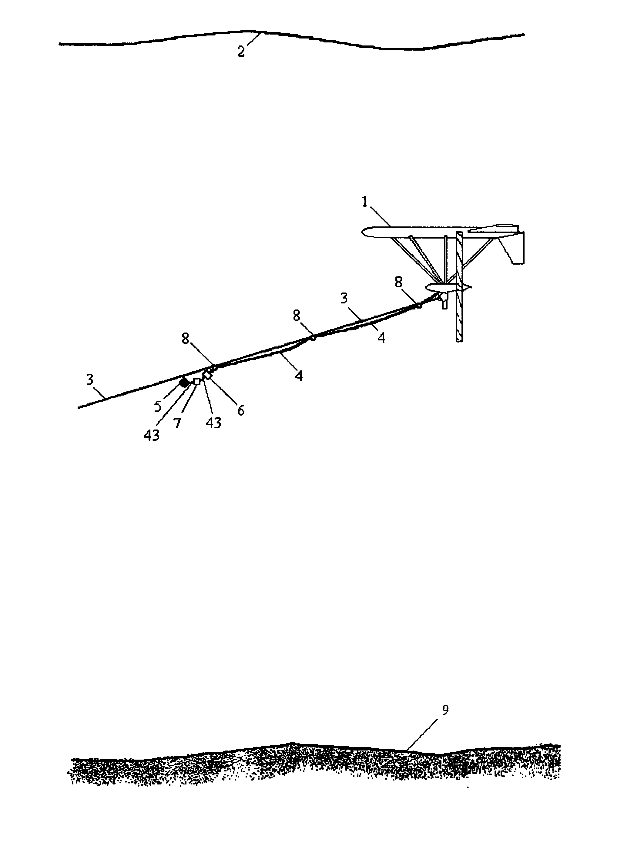
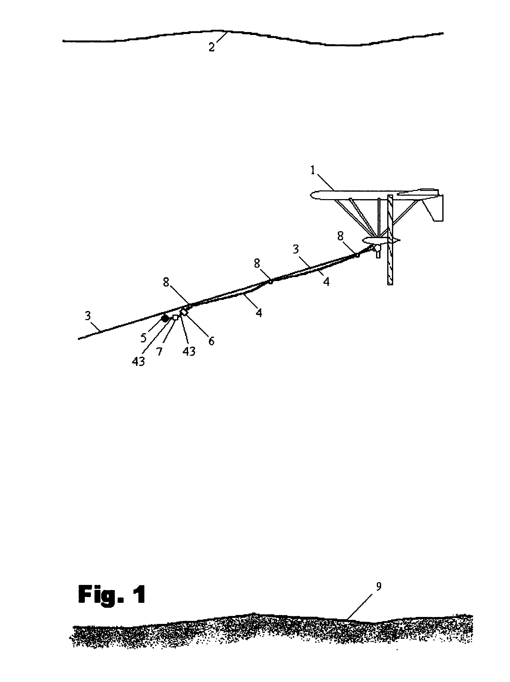
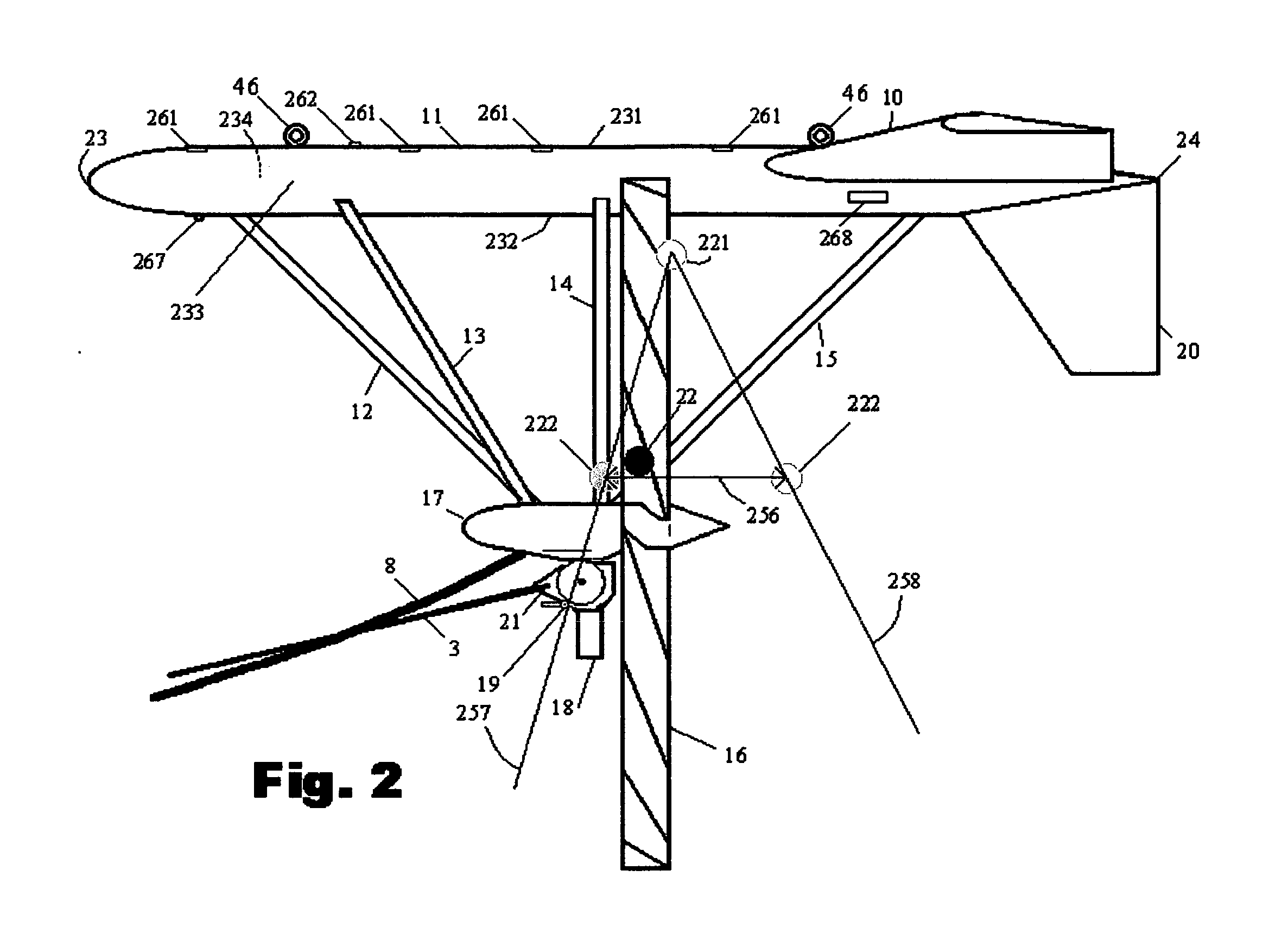
[0068] Referring now to the drawings, the present invention concerns a submersible electrical power generating plant for generating electrical power with no fuel costs from the flow of ocean current. The invention discloses a new and improved apparatus to capture the kinetic energy from the faster moving water that is near the surface of those steady currents that are the result of the Coriolis force produced by the Earth's eastward rotation acting on those currents produced by the trade winds. Instead of building giant structures that rest on the sea floor, the invention utilizes the forces produced by buoyancy, hydrodynamics, kinetic energy, leverage, weight to keep the submerged generators aligned to the current and stable at the desired depth. The invention consists of two counter-rotating, water turbines with a plurality of rotor blades extending radially outward from two separate horizontal axis that convey the kinetic energy from the two side-by-side rear-facing turbine rotor...


PUM


Abstract

A self-supporting, submersible generating plant for producing electricity from ocean currents, consisting of two counter-rotating, rear-facing turbines with a plurality of rotor blades extending radially outward from two separate horizontal axis that convey the kinetic energy from the two side-by-side, counter-rotating turbine rotors through separate gearboxes to separate generators that are housed in two watertight nacelles that are located sufficiently far apart to provide clearance for the turbine rotors. The two generators and their gearboxes serve as ballast and are located far below a streamlined buoyancy tank that extends fore and aft above and between them. A combination of a leverage system and a pressure-controlled system adjusts the hydrodynamic lifting forces to maintain constant depths. There are systems to purge the ballast water to facilitate the recovery of both individual submersible power plants and a group of many submersible power plants.

Description

BACKGROUND OF THE INVENTION [0001] 1. Field of the Invention [0002] The presently disclosed invention generally relates to improvements on a submersible electrical power generating plant. More specifically, the presently disclosed invention is primarily intended for providing an improved electrical power generating plant that is able to generate electricity from the kinetic energy contained in steady ocean currents. [0003] 2. Description of the Prior Art [0004] Perhaps the most frightening aspect about the approaching energy crisis is that so few are aware of the seriousness of the problem and the devastating impact that the worsening shortages of oil and natural gas will have upon our industrialized society, upon our nation, and upon our lives. The decline in the production of both world oil and North American natural gas—combined with catastrophic global warming—have created an urgent need to switch from fossil fuels to those energy sources that are sustainable and non-polluting. ...

Claims


Application Information

Patent Timeline
Patent Type & Authority Applications(United States)
IPC IPC(8): F03B13/00H02P9/04
CPCF03B13/264F03B17/061Y02E10/725F05B2240/97Y02E10/28F05B2240/95Y02E10/30Y02E10/72Y02P80/10Y02E10/20
Inventor ROBSON, JOHN H.
Owner ROBSON JOHN H
Why Eureka
Try Eureka