Voltage regulator with inherent voltage clamping

a voltage regulator and clamping technology, applied in the direction of electric variable regulation, process and machine control, instruments, etc., can solve the problems of complex design problems, over-voltage of regulated output, etc., and achieve the effect of compact and small area

Active Publication Date: 2007-11-08
MICROCHIP TECH INC
View PDF18 Cites 7 Cited by
  • Summary
  • Abstract
  • Description
  • Claims
  • Application Information

AI Technical Summary

Benefits of technology

[0010] The top device may be a native NMOS device, resulting in the voltage at its source terminal being approximately equal to its gate voltage when the top device is conducting a small current. As a result, when the top device is conducting a very low current, no current may flow from its gate terminal into the second node, effectively clamping the output voltage (at the source of the output NMOS device) to the intermediate voltage. The source terminal of the output NMOS device may be coupled to the non-inverting input of the OTA, thereby creating feedback loop control. As part of the OTA controlling the gate of the bottom dev

Problems solved by technology

A typical low dropout regulator may present a potential problem of producing an over-voltage of the regulated output.
This generally prese

Method used


Image

  • Voltage regulator with inherent voltage clamping
  • Voltage regulator with inherent voltage clamping
  • Voltage regulator with inherent voltage clamping

Examples


Embodiment Construction

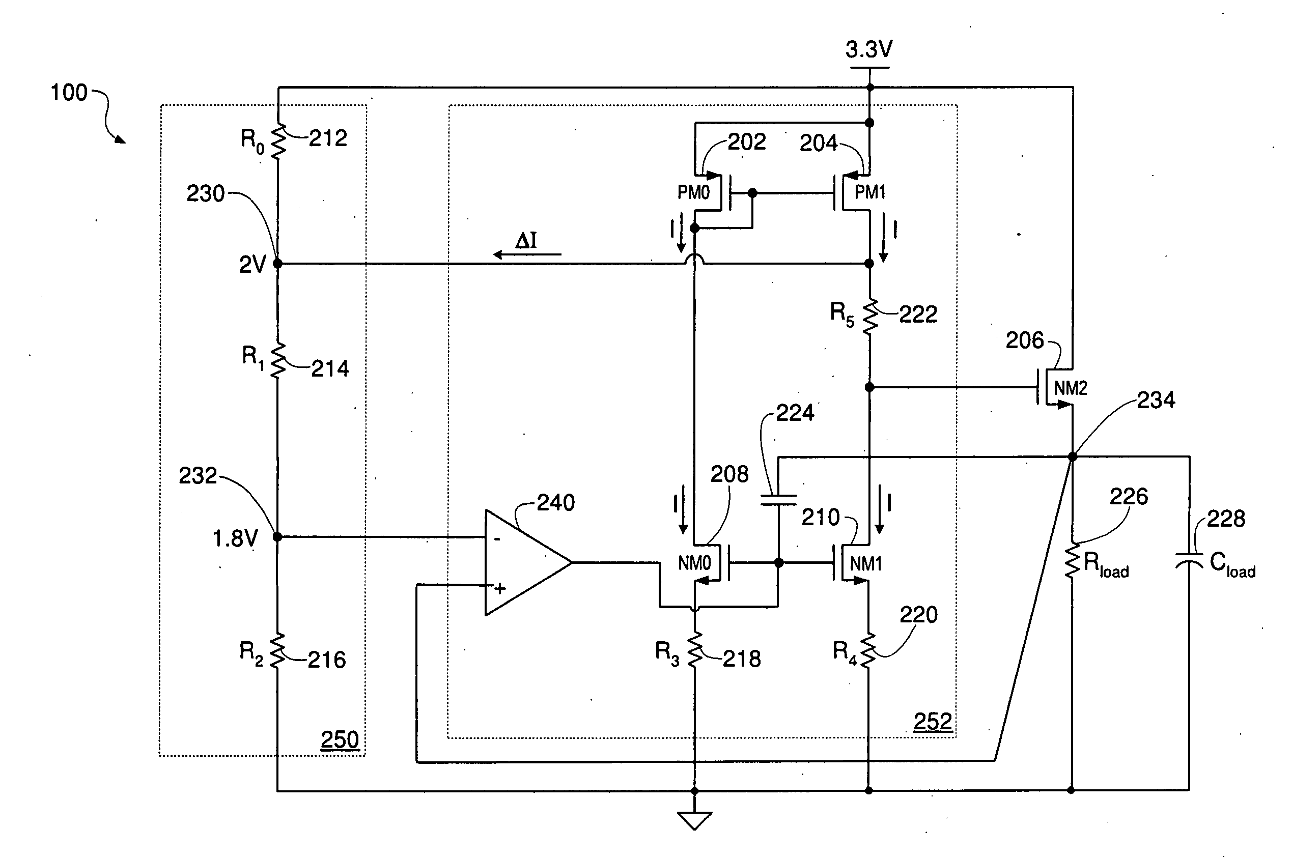
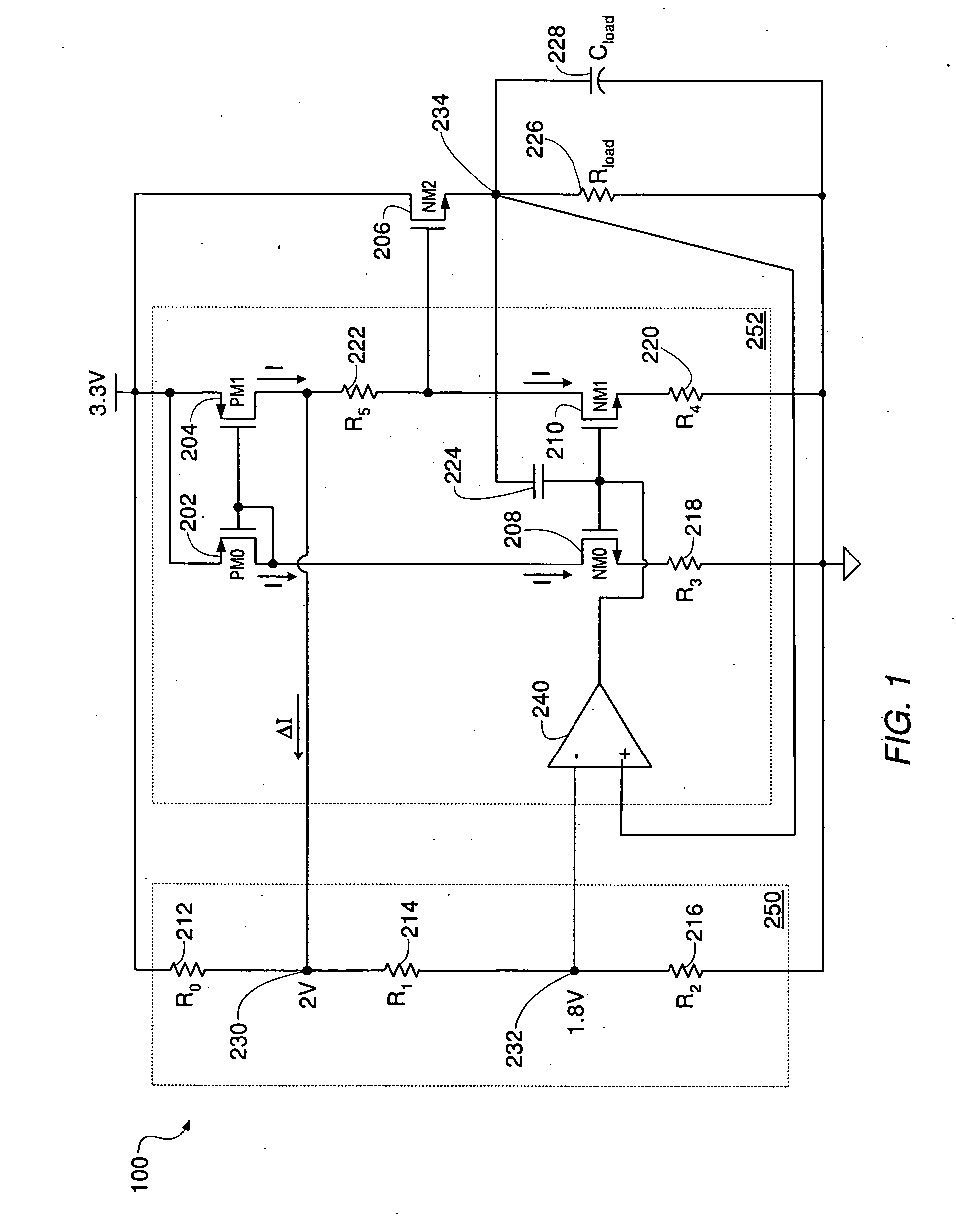
[0016]FIG. 1 shows one embodiment of a compact voltage regulator circuit 100 with inherent clamping. Voltage regulator circuit 100 may be used to provide a regulated secondary supply voltage from a primary voltage supply in a system that comprises partitions requiring two different supply voltages, thereby obviating the need for a second voltage supply. For example, a temperature sensor system may require a 3.3V supply voltage, while the monitored circuit(s) may comprise transistor devices operating from a 1.8V supply voltage. By way of example, voltage regulator circuit 100 is shown to operate from a primary supply voltage of 3.3V in order to provide a regulated 1.8V secondary supply voltage at node 234, and comprises a voltage divider circuit 250 and a control circuit 252, driving output transistor 206. Alternate embodiments may be configured with different primary voltage values for providing one of any number of different regulated secondary supply voltages as required by any gi...


PUM


Abstract

A voltage regulator may include a resistor-based voltage divider circuit generating a desired output voltage from a supply voltage, an output NMOS device whose source terminal may be configured as the output of the voltage regulator and whose drain terminal may be configured to receive the supply voltage, and a control circuit configured to control the output NMOS device to maintain the desired output voltage at the output of the voltage regulator. The control circuit may be configured to receive the desired output voltage from the voltage divider circuit as a first input, and to receive the output of the voltage regulator fed back as a second input to form a feedback loop. The control circuit may control the gate of the output NMOS device via the feedback loop to adjust the output of the voltage regulator by maintaining the desired output voltage at the source of the output NMOS device, and may also clamp the output of the voltage regulator to a specified voltage that is lower than the supply voltage, without requiring a second feedback loop.

Description

BACKGROUND OF THE INVENTION [0001] 1. Field of the Invention [0002] This invention relates generally to the field of integrated circuit design and, more particularly, to the design of voltage regulator circuits. [0003] 2. Description of the Related Art [0004] Voltage regulators are electrical regulators generally designed to automatically maintain constant voltage levels, and may operate according to electromechanical principles, or by using passive / active electronic components. In some designs, voltage regulators may be used to regulate one or more AC and / or DC voltages, performing the voltage regulation by comparing an actual output voltage to some internal fixed reference voltage. The difference between the voltages is typically amplified and used as a control signal into a control circuit configured to maintain a substantially constant output voltage, essentially forming a negative feedback control loop. If the output voltage is too low, the control circuit operates to generate ...

Claims


Application Information

Patent Timeline
IPC IPC(8): G05F1/00
CPCG05F1/565
Inventor MCLEOD, SCOTT C.
Owner MICROCHIP TECH INC
Why Eureka
Try Eureka