
Device alert system and method

a technology for alerting systems and devices, applied in frequency-division multiplexes, instruments, applications, etc., can solve the problems of difficult to determine which safety device associated with one of the various machines needs attention, time-consuming, complicated and expensive monitoring of numerous safety devices, and inability to be practical for one person, so as to improve the safety of alerts and minimize or prevent the effect of programming errors

Active Publication Date: 2007-11-08
INTERMOUNTAIN INTELLECTUAL ASSET MANAGEMENT LLC
View PDF44 Cites 133 Cited by
  • Summary
  • Abstract
  • Description
  • Claims
  • Application Information

AI Technical Summary

Benefits of technology

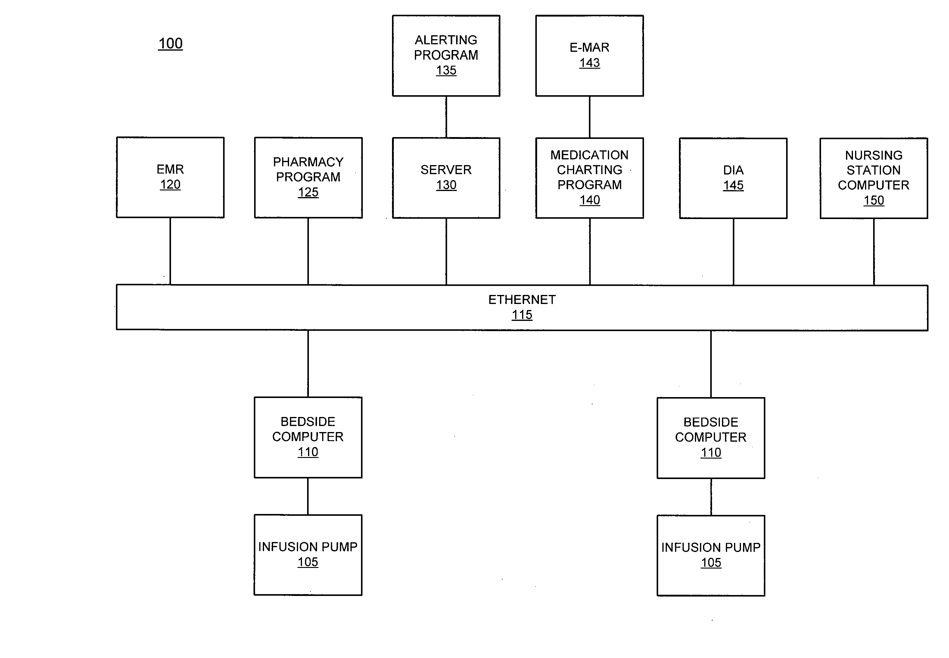
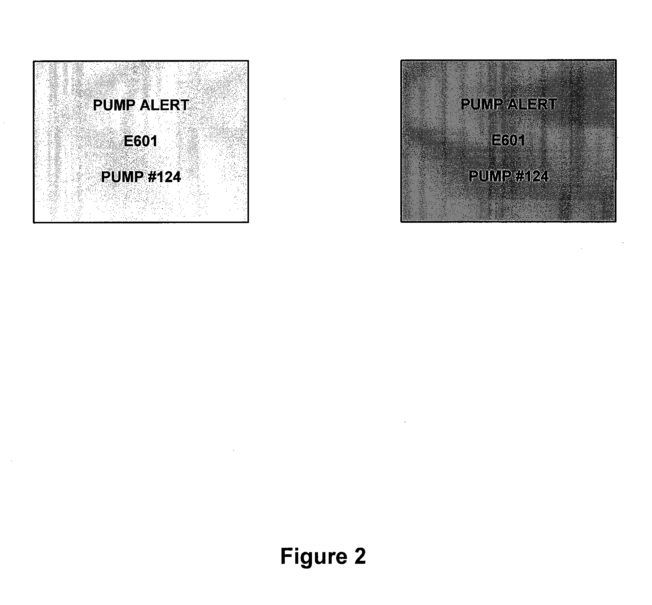
[0010]The present invention includes a system and method for providing an enhanced safety alert for a device. The invention minimizes or prevents the affects of programming errors and / or provides more specific alert information to a monitoring person, wherein the alert information may relate to a potential safety concern. The method includes monitoring data transmitted from a device (e.g., infusion pump, etc) and comparing the data to pre-established rules. When the data violates the rules (e.g., a programming rule based on rate percentage increases, unit specific protocols, etc.), or triggers an internal alarm (e.g., breathing changes, disconnections, etc.), the system compiles an alert information packet, wherein the alert information packet includes information related to the device and the data. The system then transmits the alert information packet to multiple healthcare providers, locations, and / or communication devices (e.g., multiple computer screens in a particular area).

Problems solved by technology

In some situations, a malfunctioning device or an inappropriate amount of materials may cause significant problems.
While an increasing number of machines include safety devices (e.g., automatic shut-off, monitoring gauges, alarms, etc), it is often time-consuming, complicated and expensive to monitor numerous safety devices.
More specifically, if the machines are located in different areas, it may not be practical for one person to be able to monitor all the machines at one time.
Moreover, when many machines are in a certain area, it may be difficult to determine which safety device associated with one of the various machines needs attention.
As such, the monitoring person is not able to quickly determine if the alarm is a critical issue, or a minor malfunction.
As a result, the monitoring person typically spends valuable time diagnosing the problem.
For example, an incorrectly programmed infusion pump 105 or a disconnection of a ventilator imposes a serious safety threat to patients.
Incorrectly programmed infusion pumps 105 or disconnected ventilators may result in a significant number of incident reports and alerts.
Some of the incidents may result in a physiological change in a patient due to the incorrectly programmed pump.
Furthermore, eExisting infusion pumps 105 (e.g., smart pump technology) do not prevent programming errors based on rate percentage increases or unit specific protocols.
Moreover, certain high-risk medications have narrow therapeutic indexes and require careful titration for maximal effect.
However, a study of 64 anesthetists assessed 10 common operating room alarms for perceived urgency and only 33 percent were correctly identified.
), too often the resulting alarms go unnoticed for excessive periods of time.
This results from a system problem that is outside of the control of the ventilator.
This may be due to, for example, the physical layout of the ICU, staffing limitations, staff complacency due to numerous false alarms and / or environmental acoustics and noise.
Another serious problem is when patients who are in isolation for infection experience a critical ventilator event.
In some situations, the ventilator alarm is heard, but valuable time can be lost while the clinician tries to determine which patient or room in the unit activated the alarm.
Moreover, current systems do not provide respiratory care management with information on the duration of the critical events, especially with regard to ventilator disconnections.

Method used


Image

  • Device alert system and method
  • Device alert system and method
  • Device alert system and method

Examples


Embodiment Construction

[0017]The detailed description of exemplary embodiments herein makes reference to the accompanying figures, which show the exemplary embodiment by way of illustration and its best mode. While these exemplary embodiments are described in sufficient detail to enable those skilled in the art to practice the invention, it should be understood that other embodiments may be realized and that logical and mechanical changes may be made without departing from the spirit and scope of the invention. Thus, the detailed description herein is presented for purposes of illustration only and not of limitation. For example, the steps recited in any of the method or process descriptions may be executed in any order and are not limited to the order presented. Moreover, any of the functions or steps may be outsourced to or performed by one or more third parties. Furthermore, any reference to singular includes plural embodiments, and any reference to more than one component may include a singular embodi...


PUM


Abstract

A system and method for providing a safety alert for a device is disclosed. The invention minimizes or prevents the affects of programming errors and / or provides enhanced alert information to a monitoring healthcare provider, wherein the alert information may relate to a potential safety concern. The method includes monitoring data transmitted from a device (e.g., infusion pump) and comparing the data to pre-established rules. When the data violates the rules, the system compiles an alert information packet, wherein the alert information packet includes information related to the device and the data. The system then transmits the alert information packet and / or an enhanced alert to multiple computer screens in a particular area.

Description

CROSS-REFERENCE TO RELATED APPLICATIONS[0001]This application claims priority to, and the benefit of, U.S. Provisional Application Ser. No. 60 / 746,734, filed on May 8, 2006 and entitled “Device Alert System and Method,” the entire contents of which is hereby incorporated by reference.FIELD OF INVENTION[0002]The invention generally relates to device alerts, and more particularly, to alerts which minimize the affects of programming errors and / or provide substantive alert information to multiple people.BACKGROUND OF THE INVENTION[0003]In many industries, it is very important for certain devices to operate appropriately, and for the appropriate amount of materials to be utilized. In some situations, a malfunctioning device or an inappropriate amount of materials may cause significant problems. While an increasing number of machines include safety devices (e.g., automatic shut-off, monitoring gauges, alarms, etc), it is often time-consuming, complicated and expensive to monitor numerous ...

Claims


Application Information

Patent Timeline
IPC IPC(8): G08B29/00A61B5/00G08B1/00G06N5/02G08B19/00
CPCA61B5/0002A61B5/412G08B29/24G08B5/222G08B25/04G06N5/04G16H40/67Y10S128/903
Inventor CARLSON, RICKEVANS, R. SCOTTPALMER, BRENTJOHNSON, KYLEFLINT, VRENA B.
Owner INTERMOUNTAIN INTELLECTUAL ASSET MANAGEMENT LLC
Learn More