System and method for turbine engine fault detection using discrete event system modeling

a turbine engine and event system technology, applied in the field of diagnostic systems, can solve the problems of increasing the need for automatic prognosis and fault detection systems, the inability to easily apply explicit knowledge to extracted features, and the complexity of modern mechanical systems. achieve the effect of improving fault diagnosis and prognosis

Active Publication Date: 2007-11-08
HONEYWELL INT INC
View PDF61 Cites 62 Cited by
  • Summary
  • Abstract
  • Description
  • Claims
  • Application Information

AI Technical Summary

Benefits of technology

[0007] The present invention provides a system and method for fault detection in a turbine engine. The fault detection system and method uses discrete event system modeling to provide improved fault diagnosis and prognosis. The fault detection system and method receives sensor taken at multiple dynamic events occurring in different time windows. An event determination mechanism evaluates the received sensor data to determine if specified events have occurred. Indications of the occurrence of specified events are then passed to a discrete event system model. The discrete event system model analyzes the timing and sequencing of the event occurrences to determine if a fault has occurred. This method does not require a detailed modeling of the system, and thus can be applied to complex systems such as turbine engines.

Problems solved by technology

Modern mechanical systems can be exceedingly complex.
The complexities of modem mechanical systems have led to increasing needs for automated prognosis and fault detection systems.
However, this type of approach will suffer in applications where explicit knowledge cannot be easily applied to extracted features.
For example, where different types of failures are expressed in evidences spread over different durations of times. In these cases the disparity in space and time can interfere with the ability of interpret the sensor data and limit the effectiveness of the fault detection.

Method used


Image

  • System and method for turbine engine fault detection using discrete event system modeling
  • System and method for turbine engine fault detection using discrete event system modeling
  • System and method for turbine engine fault detection using discrete event system modeling

Examples


Embodiment Construction

[0017] The present invention provides a system and method for fault detection in a turbine engine. The fault detection system and method uses discrete event system modeling to provide improved fault diagnosis and prognosis. This method does not require a detailed modeling of the system, and thus can be applied to complex systems such as turbine engines. The fault detection system and method can implemented to detect a wide range of faults on a variety of turbine engines. For example, the system and method can be implemented to detect faults on turbine engines used for vehicle propulsion (e.g., aircraft) and for power generation (e.g., aircraft auxiliary power units, electricity generation).

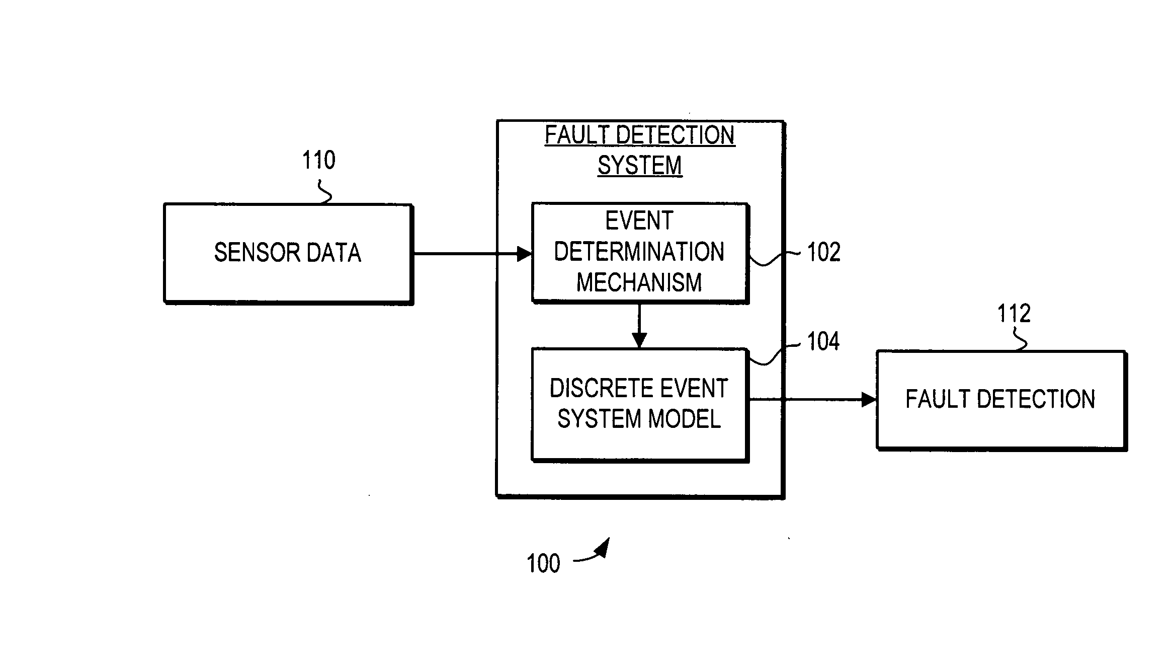
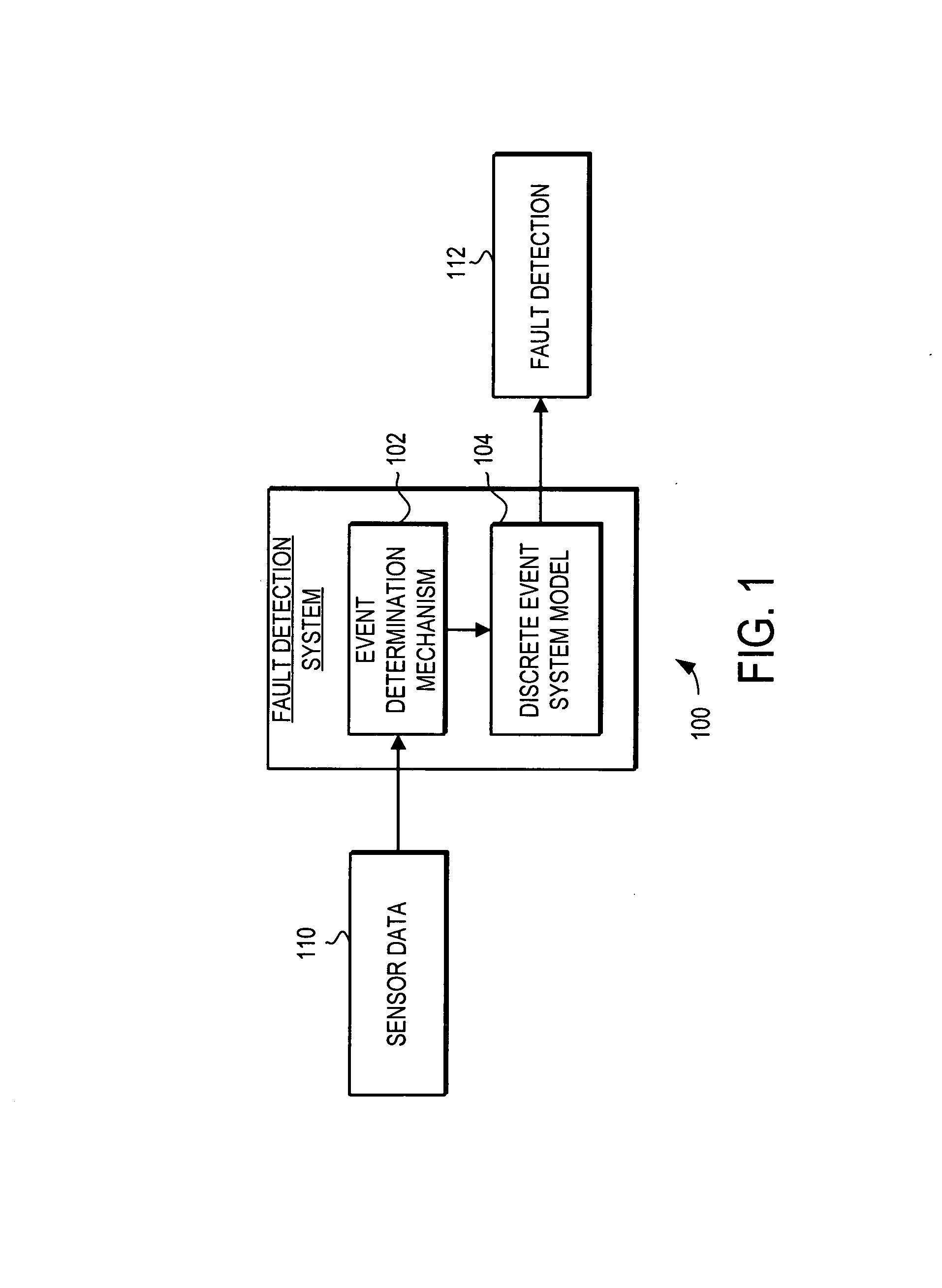
[0018] Turning now to FIG. 1, a schematic view of a fault detection system 100 is illustrated. The fault detection system 100 includes an event determination mechanism 102 and a discrete event system model 104. The fault detection system 100 receives sensor data 110 taken at multiple dynamic even...


PUM


Abstract

A system and method is provided for fault detection in a turbine engine. The fault detection system and method uses discrete event system modeling to provide improved fault diagnosis and prognosis. The fault detection system and method receives sensor taken at multiple dynamic events occurring in different time windows. An event determination mechanism evaluates the received sensor data to determine if specified events have occurred. Indications of the occurrence of specified events are then passed to a discrete event system model. The discrete event system model analyzes the timing and sequencing of the event occurrences to determine if a fault has occurred. This method does not require a detailed modeling of the system, and thus can be applied to complex systems such as turbine engines.

Description

FIELD OF THE INVENTION [0001] This invention generally relates to diagnostic systems, and more specifically relates to prognosis systems for mechanical systems. BACKGROUND OF THE INVENTION [0002] Modern mechanical systems can be exceedingly complex. The complexities of modem mechanical systems have led to increasing needs for automated prognosis and fault detection systems. These prognosis and fault detection systems are designed to monitor the mechanical system in an effort to predict the future performance of the system and detect potential faults. These systems are designed to detect these potential faults such that the potential faults can be addressed before the potential faults lead to failure in the mechanical system. [0003] One type of mechanical system where prognosis and fault detection is of particular importance is aircraft systems. In aircraft systems, prognosis and fault detection can detect potential faults such that they can be addressed before they result in serious...

Claims


Application Information

Patent Timeline
Patent Type & Authority Applications(United States)
IPC IPC(8): G06F19/00
CPCF01D21/00F01D21/003F01D21/14F05D2270/44Y10T477/633F05D2270/09F05D2270/709Y10T477/40F05D2270/708G05B23/0235
Inventor KIM, KYUSUNGMYLARASWAMY, DINKARSTURM, DOUG
Owner HONEYWELL INT INC
Why Eureka
Try Eureka