
Modular Engine Cover

a module engine and cover technology, applied in the field of covers, can solve the problems of requiring significant tooling costs for modifications to this type of cover to accommodate engines with different service item locations, and achieve the effect of reducing tooling and manufacturing costs and reducing the weight of the engine cover

Inactive Publication Date: 2007-11-15
FORD GLOBAL TECH LLC
View PDF14 Cites 13 Cited by
  • Summary
  • Abstract
  • Description
  • Claims
  • Application Information

AI Technical Summary

Benefits of technology

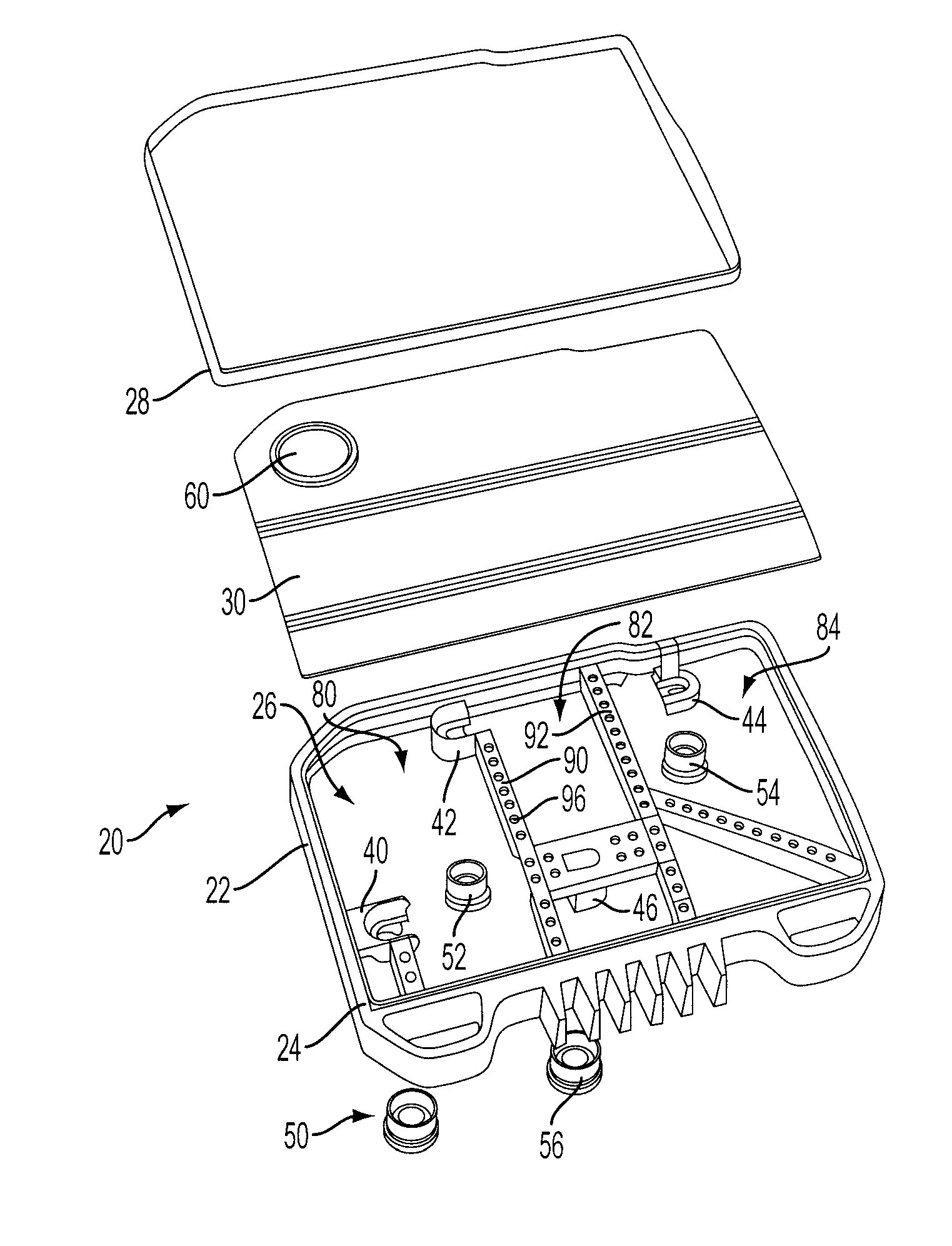
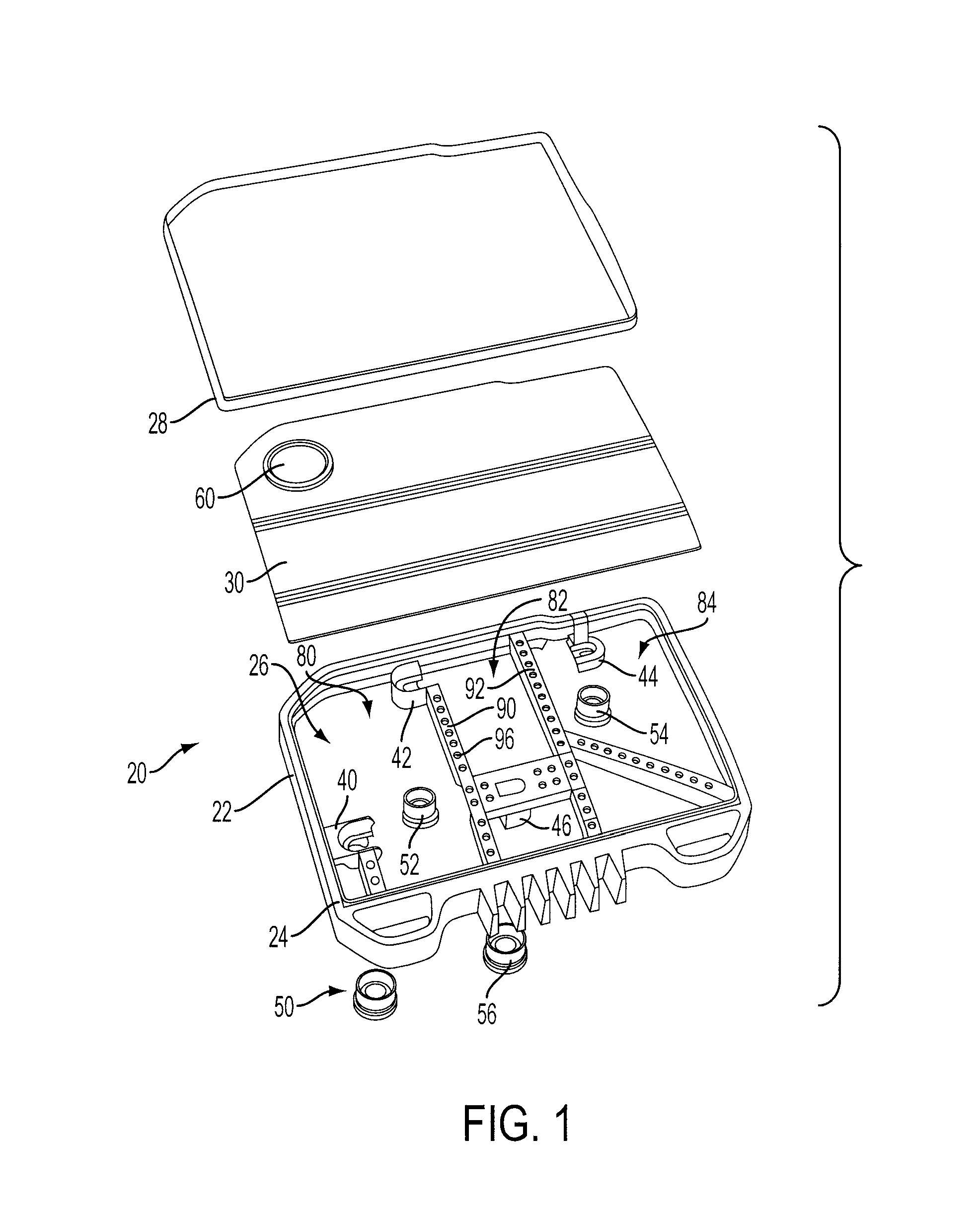
[0006] An engine cover for a vehicle includes a frame extending generally about the perimeter of the cover and adapted for mounting to an engine of the vehicle, and a skin extending across and secured to the frame. In one embodiment, the frame is made of a molded plastic material and the skin is a stamped metal, such as aluminum. In another embodiment, the skin comprises multiple sections each secured to the frame so that one or more sections may be modified to alter the appearance of the cover and / or location of service items, such as an oil fill cap or dip stick for different applications while minimizing the number of components and associated costs that need modification. One or more isolators may be secured to the frame and adapted for mounting on the engine to reduce or eliminate cover vibration and associated noise during operation of the engine.
[0008] The present invention provides a number of advantages. For example, the present invention reduces weight of the engine cover while providing a common bridge structure that may be used for multiple engine applications to reduce tooling and manufacturing costs. An engine cover with a modular structure according to the present invention allows use of multiple skins to change the overall appearance in addition to accommodating different location of service items, such as an oil fill hole or dip stick location, for example.

Problems solved by technology

The engine compartment of a vehicle presents various challenges for vehicle engineers and designers in providing functionality, serviceability, and aesthetics in a relatively small space.
Modifications to this type of cover to change the appearance or to accommodate engines with different service item locations typically require significant tooling costs.

Method used


Image

  • Modular Engine Cover
  • Modular Engine Cover
  • Modular Engine Cover

Examples


Embodiment Construction

)

[0020] As those of ordinary skill in the art will understand, various features of the present invention as illustrated and described with reference to any one of the Figures may be combined with features illustrated in one or more other Figures to produce embodiments of the present invention that are not explicitly illustrated or described. The combinations of features illustrated provide representative embodiments for typical applications. However, various combinations and modifications of the features consistent with the teachings of the present invention may be desired for particular applications or implementations.

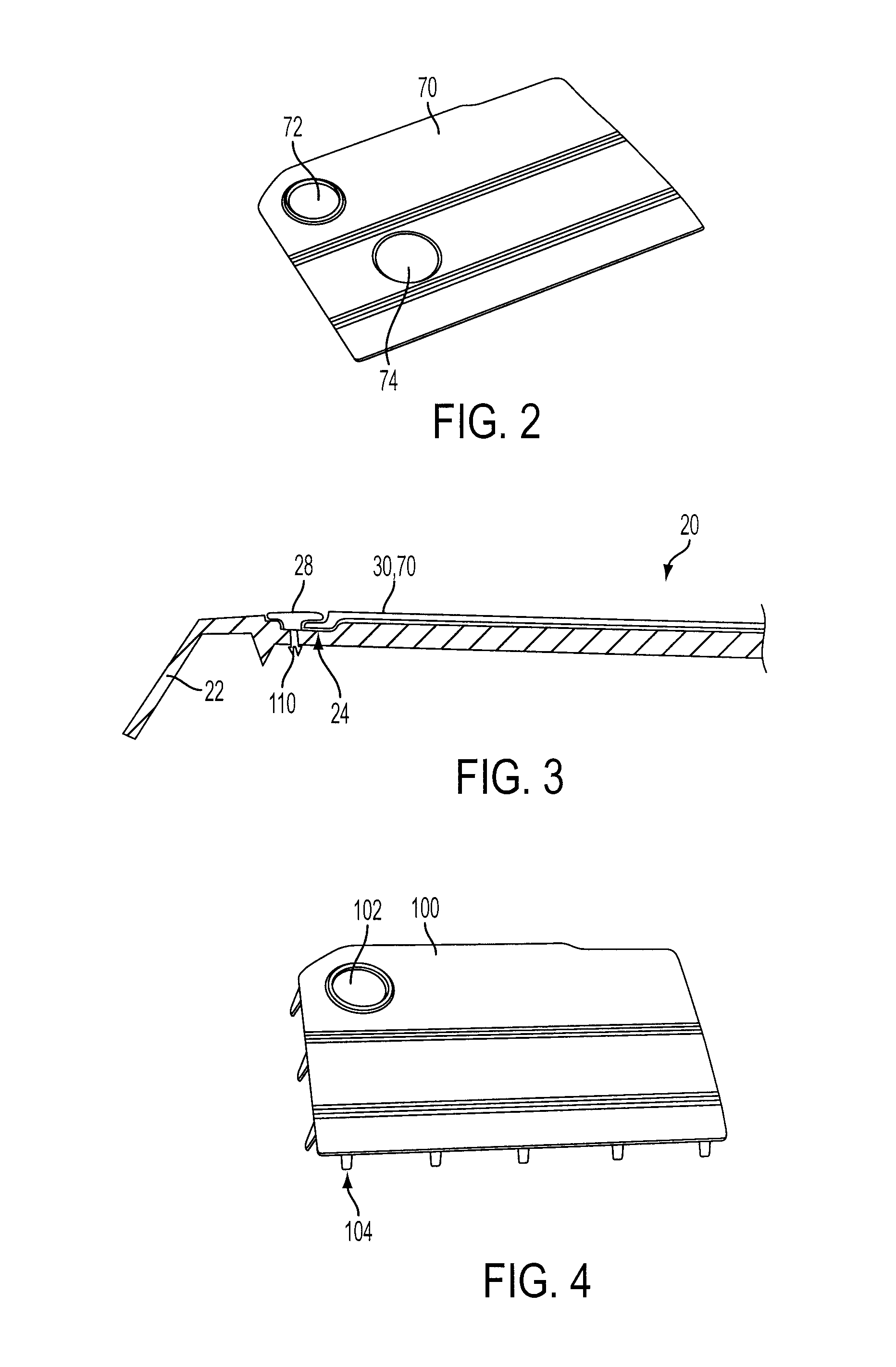
[0021] Referring now to FIG. 1, an engine cover 20 includes a frame 22 extending generally about the perimeter of cover 20. In the embodiment illustrated in FIG. 1, frame 22 includes a recess or groove 24 (best shown in FIG. 3) extending around a main opening 26 and adapted to receive a retainer 28 to secure cover plate 30 to frame 22. A plurality of receivers or mou...


PUM


Abstract

An engine cover for a vehicle includes a frame extending generally about the perimeter of the cover and adapted for mounting to an engine of the vehicle, and a skin extending across and secured to the frame. In one embodiment, the frame is made of a moulded plastic material and the skin is a stamped metal, such as aluminum. In another embodiment, the skin comprises multiple sections each secured to the frame so that one or more sections may be modified to alter the appearance of the cover and / or location of service items, such as an oil fill cap or dip stick for different applications while minimizing the number of components that need modification. A method for covering an engine according to the present invention includes securing at least one engine cover skin to an engine cover frame and securing the frame to an engine.

Description

BACKGROUND OF THE INVENTION [0001] 1. Field of the Invention [0002] The present invention relates to a cover for a vehicle engine. [0003] 2. Background Art [0004] The engine compartment of a vehicle presents various challenges for vehicle engineers and designers in providing functionality, serviceability, and aesthetics in a relatively small space. Consideration must also be given to manufacturing and assembly costs in addition to weight, which ultimately impacts fuel economy, to deliver a competitive product. An engine cover may be used to enhance the overall appearance of the engine compartment and may also reduce engine noise transmission. [0005] Various prior art engine covers provide a cast or molded cover with a solid, generally rectangular surface that extends across the engine cylinders, such as disclosed in US 2005 / 0217634 A1, for example. Modifications to this type of cover to change the appearance or to accommodate engines with different service item locations typically r...

Claims


Application Information

Patent Timeline
IPC IPC(8): F02M35/02
CPCF01M2011/0491F02M35/04F02F7/006
Inventor FOGOLINI, JIMMEY
Owner FORD GLOBAL TECH LLC
Learn More