

Sliding Armrest
- Summary
- Abstract
- Description
- Claims
- Application Information
AI Technical Summary
Benefits of technology
Problems solved by technology
Method used
Image

Examples
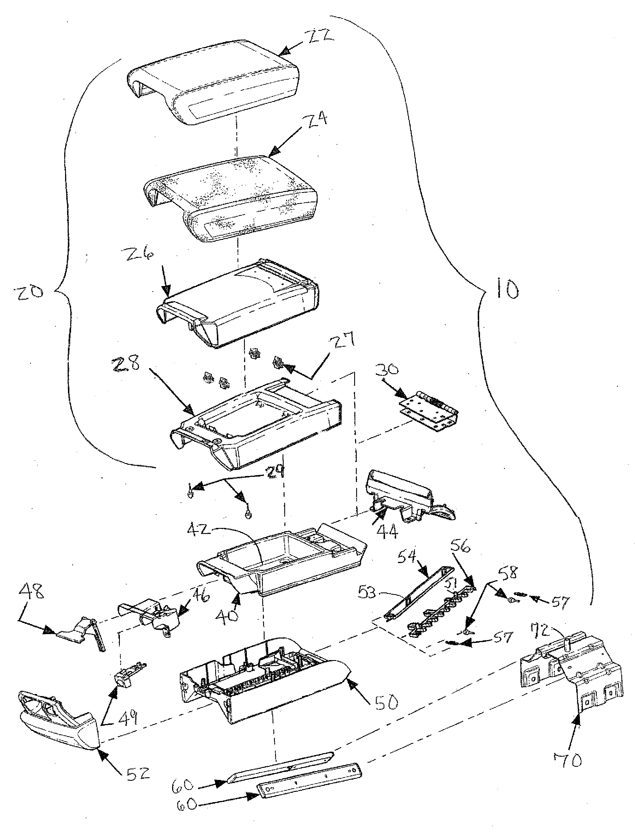
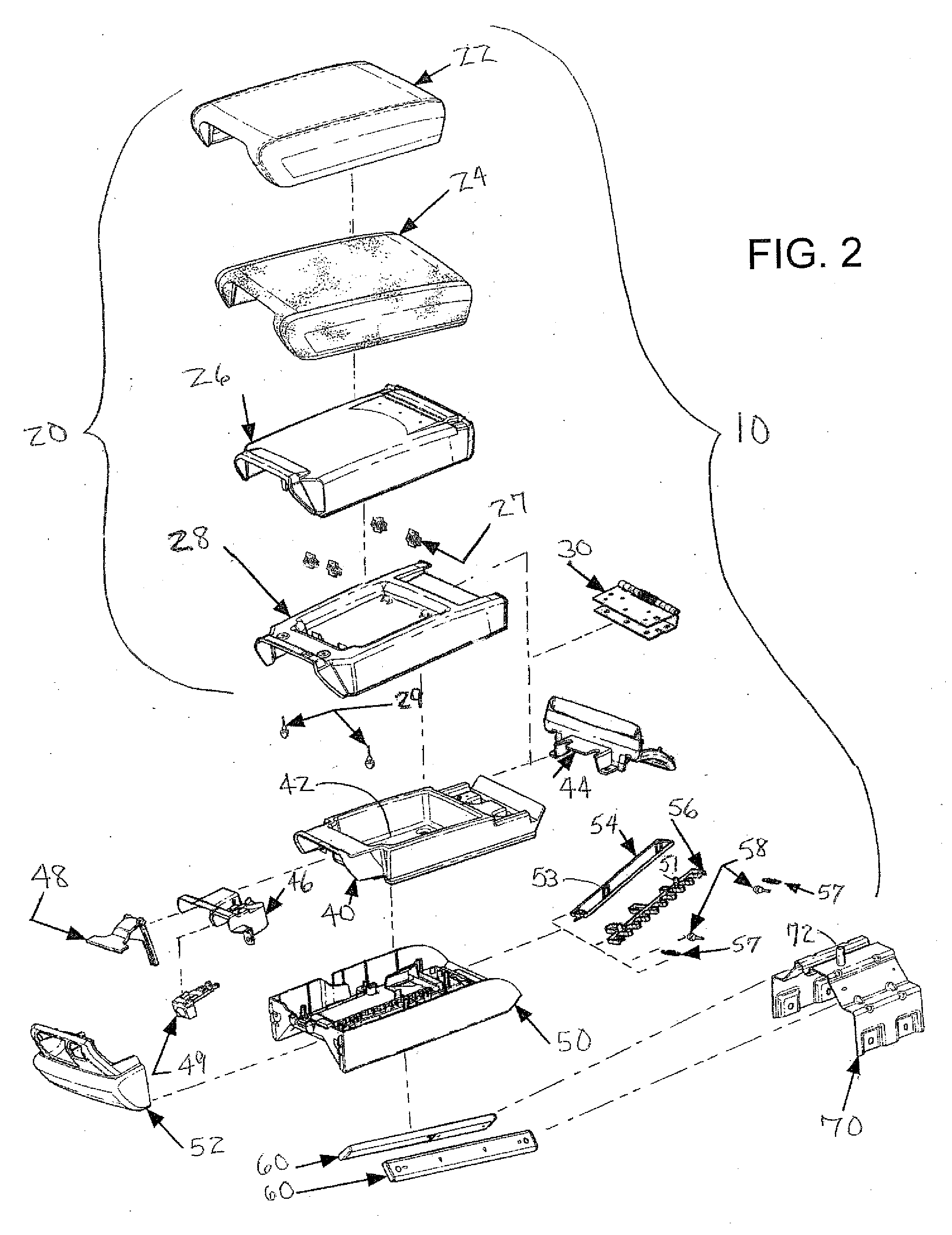
first embodiment
[0027] For elements common to the various embodiments of the invention, the numerical reference character between the embodiments is held constant, but distinguished by the addition of an alphanumeric character to the existing numerical reference character. In other words, for example, an element referenced at 10 in the first embodiment is correspondingly referenced at 10A, 10B, and so forth in subsequent embodiments. Thus, where an embodiment description uses a reference character to refer to an element, the reference character applies equally, as distinguished by alphanumeric character, to the other embodiments where the element is common.
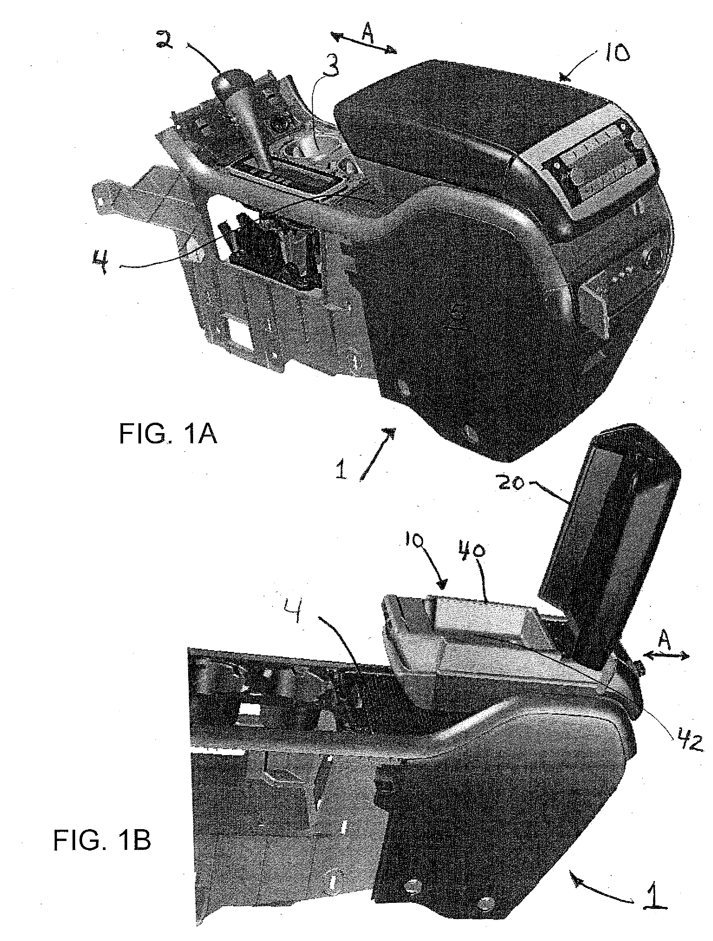
[0028] An exemplary embodiment of the sliding armrest according to the present invention is shown in perspective view in FIGS. 1A and 1B. FIG. 1A is a perspective view of a center console for a transportation vehicle such as would be positioned between the front seats of that vehicle. Alternatively, a similar console, without the shifting mechani...
second embodiment
[0049] the actuating mechanism which releasably connects the base portion 50 to the reinforcement or support bracket 70 will now be described. A detent plate 156 including one or more projections 110 may be loosely held in place on the bracket by detent housing 153 (see FIG. 11). Springs 157 may be located between the detent plate 156 and the support bracket 70 and may bias the plate against the housing. The cable assembly 154 may attach at one end to latch handle 148 and at the opposite end attach to the detent plate 156. When the hatch handle 148 is squeezed, it may pull on the wire in cable assembly 154 causing the detent plate 156 to move downward and compress springs 157 against reinforcement 70.
[0050] The center area of base portion 50 may be formed into one or more rows 151 of inverted depressions 100 (see FIG. 10) which may engage the projections 110 on the detent plate 156 (see FIG. 11) to latch the armrest 10 in selected fore / aft positional locations. Retraction of the pro...
PUM
 Abstract
Description
Claims
Application Information