RF passive repeater for a metal container

Active Publication Date: 2007-11-15
ASSA ABLOY AB
View PDF29 Cites 33 Cited by
  • Summary
  • Abstract
  • Description
  • Claims
  • Application Information

AI Technical Summary

Benefits of technology

[0009] An advantage of the present invention is that data can be transmitted to and read from the RFID tags within the metal enclosure without having to open or remove the tagged equipment fro

Problems solved by technology

This “virtual” contact requirement makes communication with a surgical implant device or

Method used


Image

  • RF passive repeater for a metal container
  • RF passive repeater for a metal container
  • RF passive repeater for a metal container

Examples


Embodiment Construction

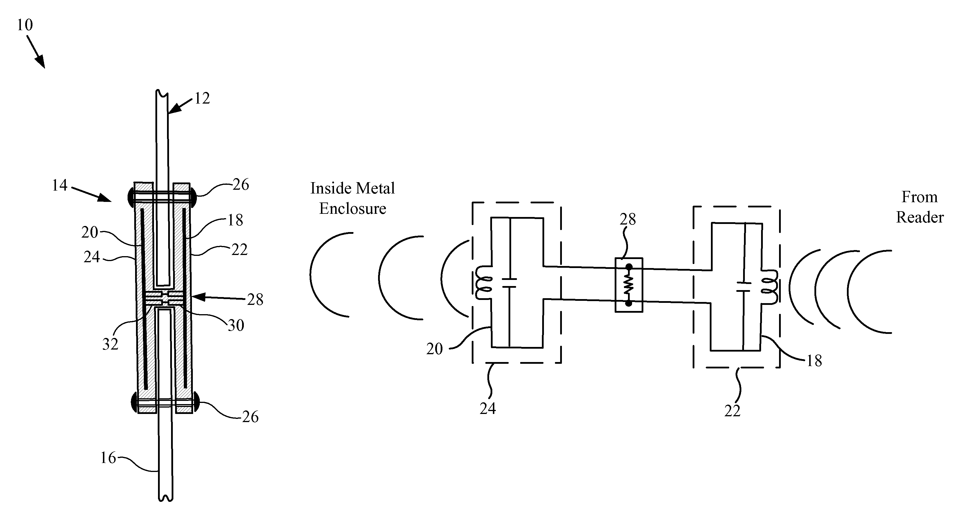
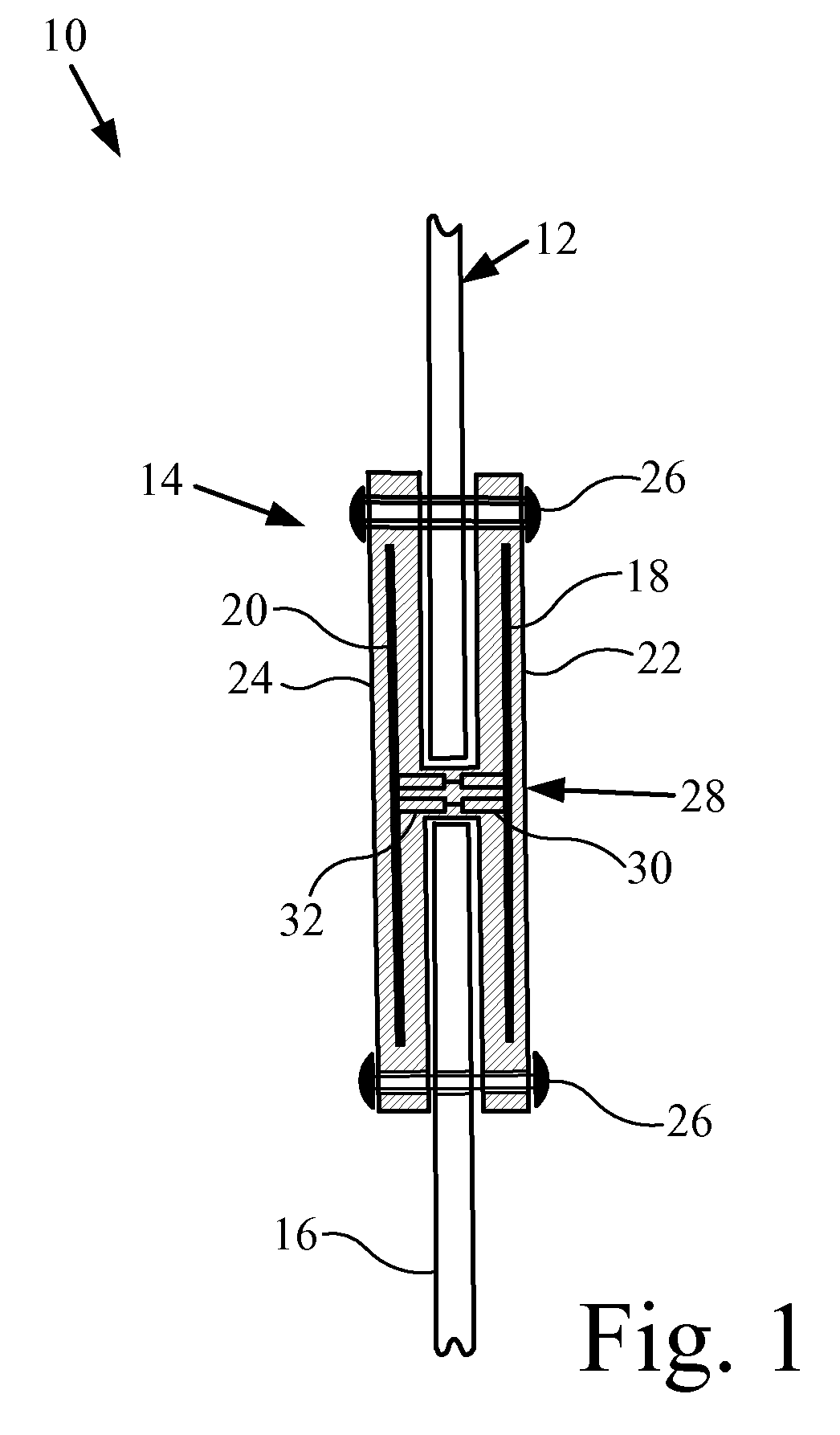
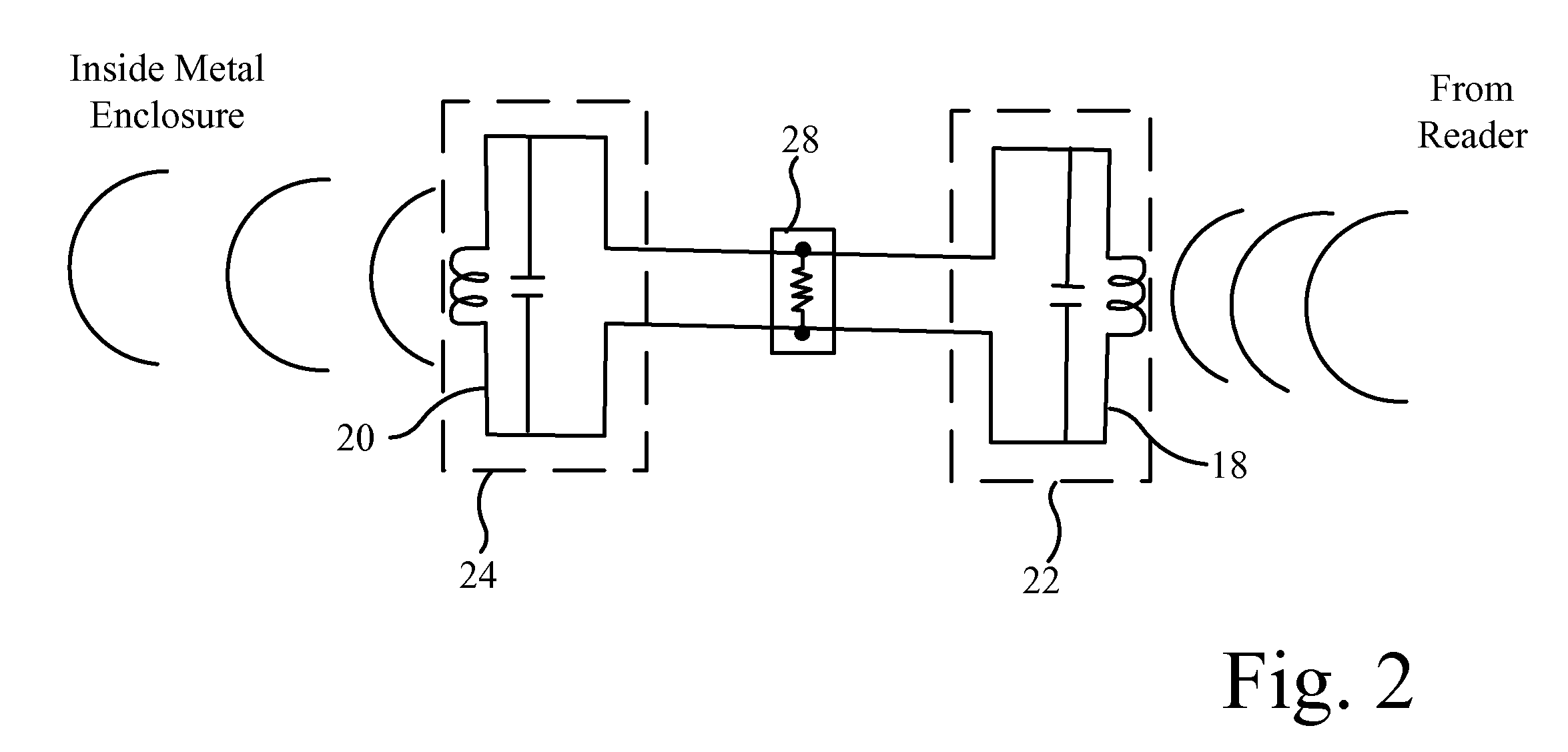
[0015] Referring now to FIGS. 1 and 2, there is shown an embodiment of a storage container assembly 10 of the present invention which generally includes a metal container 12 and an antenna assembly in the form of a passive wireless repeater 14. Metal container 12 is preferably configured to hold orthopaedic instruments or implants, but may also be configured to hold any type of equipment carrying RFID tags. The term “container”, as used herein, is intended to broadly mean any type of container, enclosure, case, tray, etc. with RFID tagged equipment therein. The term “equipment”, as used herein, is intended to broadly mean any type of product which is tagged with RFID tags, such as orthopaedic instruments or implants, non-orthopaedic products, etc.

[0016] Container 12 includes a plurality of metal side walls 16, one of which is shown in FIG. 1. The term “side wall”, as used herein, is intended to mean any wall of container 12. Passive wireless repeater 14 is mounted on side wall 16, ...


PUM


Abstract

A storage container assembly includes a container having a metal side wall, and a passive wireless repeater mounted on the side wall. The repeater includes a first antenna on one side of the side wall, a second antenna on an opposite side of the side wall, and an electrical connection between the first antenna and the second antenna. The electrical connection may be in the form of a first connector mounted to the first antenna and a second connector mounted to the second antenna.

Description

CROSS REFERENCE TO RELATED APPLICATIONS [0001] This is a non-provisional application based upon U.S. provisional patent application Ser. No. 60 / 800,093, entitled “RF METALLIC ENCLOSURE PASSIVE REPEATER”, filed May 12, 2006. BACKGROUND OF THE INVENTION [0002] 1. Field of the Invention [0003] The present invention relates to RFID tags, and, more particularly, to techniques for transmitting RF signals to and from such RFID tags. [0004] 2. Description of the Related Art [0005] Radio frequency identification (RFID) tags are well known throughout industry, and are being increasingly utilized for supply chain management, inventory management, and logistic control. These tags can be written to and read from a handheld transceiver or fixed portal. Small low frequency tags are currently being utilized in surgical tools and implantable devices. These small tags are frequently carried in a metal enclosure with small holes designed to allow the tools or implants to be sterilized using a high hea...

Claims


Application Information

Patent Timeline
IPC IPC(8): G08B13/14G08B1/08
CPCG06K19/07749G06K19/0723
Inventor WESTRICK, MICHAEL D.SANDS, DANIEL L.
Owner ASSA ABLOY AB
Why Eureka
Try Eureka