Storage apparatus, defect check method, and program

a technology of defect check and storage apparatus, applied in the field of storage apparatus, can solve the problems of defect check of such a storage apparatus supporting a plurality of sector lengths, consume man-hours, and difficult to make a production plan, so as to reduce the processing load of the defect check, reduce the buffer capacity required in the process, and shorten the processing time

a technology of defect check and storage apparatus, applied in the field of storage apparatus, can solve the problems of defect check of such a storage apparatus supporting a plurality of sector lengths, consume man-hours, and difficult to make a production plan, so as to reduce the processing load of the defect check, reduce the buffer capacity required in the process, and shorten the processing time

US20070263313A1Inactive Publication Date: 2007-11-15TOSHIBA STORAGE DEVICE CORP

Image

  • Storage apparatus, defect check method, and program
  • Storage apparatus, defect check method, and program
  • Storage apparatus, defect check method, and program

Examples


Embodiment Construction

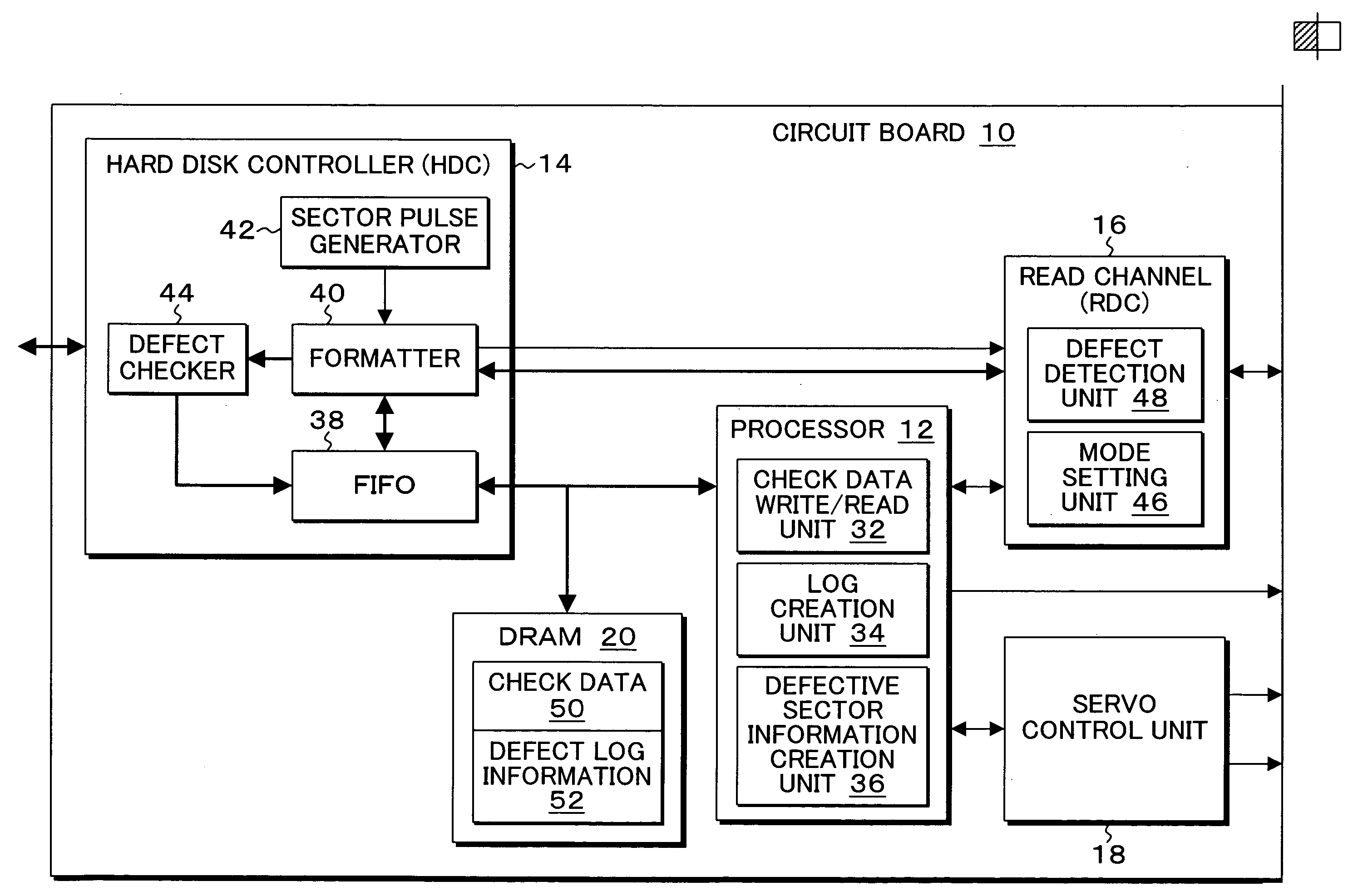
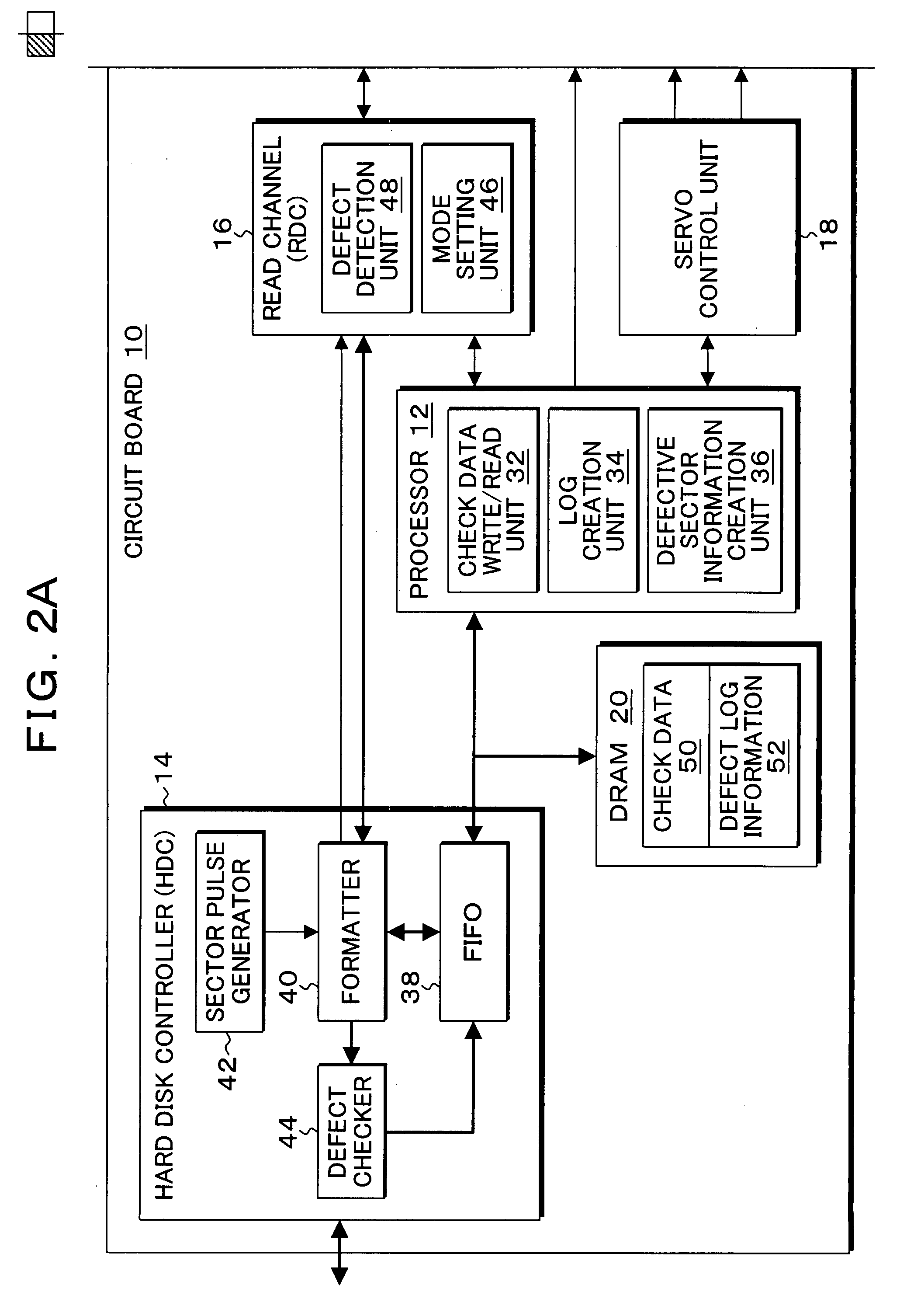
[0056]FIGS. 2A and 2B are block diagrams of a magnetic disk apparatus to which a defect check process according to the present invention is applied. In FIGS. 2A and 2B, the magnetic disk apparatus, which is known as a hard disk drive (HDD) is composed of a circuit board 10 and a disk enclosure 11. In the circuit board 10, a processor 12, a hard disk controller (HDC) 14, a read channel (RDC) 16, a servo control unit 18, and a DRAM 20 are provided. In the disk enclosure 11, a read / write amplifier 24, a head assembly 26, a voice coil motor 28, and a spindle motor 30 are provided. One or a plurality of magnetic disk media, which are not shown, are attached to a rotating shaft of the spindle motor 30 and rotated at a constant speed. The head assembly 26 is supported by a distal end of an arm of a head actuator, and, when the head actuator is driven by the voice coil motor 28, the head assembly 26 having a read head and a write head is positioned with respect to the medium surface of the ...


PUM

PropertyMeasurementUnit
defectaaaaaaaaaa
lengthaaaaaaaaaa
defect detectionaaaaaaaaaa

Abstract

A check data write / read unit writes and reads check data of defects in data frame units between servo frames recorded on a medium. A read channel of the check data write / read unit outputs defect detection data in which analog variations due to medium defects such as levels and shifts of a head read signal are determined. A log creation unit creates log information from the defect detection data which is generated through reading of the check data in the data frame units. A defective sector information creation unit creates, through analysis of the log information, and saves a defective sector map indicating positions of defective sectors in a predetermined sector length.

Description

[0001] This application is a continuation of PCT / JP2005 / 003004, filed Feb. 24, 2005.TECHNICAL FIELD [0002] The present invention relates to a storage apparatus, a defect check method, and a program which generate defective sector information by checking defects of a medium such as a magnetic disk and, in particular, relates to a storage apparatus, a defect check method, and a program which can create defective sector information supporting sector formats of different sector lengths. BACKGROUND ART [0003] Conventionally, in a method which checks defects (defects) of a medium in a storage apparatus such as a hard disk drive, the sector length is fixed to, for example, 512 bytes, and defects of the medium are checked in sector units by using the fixed sector length. In the defect check, check data is written in the fixed sector lengths, then read in the sector units, and stored in a buffer; defect positions are detected in the buffer from patterns that are different from expected value...

Claims


Application Information

Patent Timeline
15 Nov 2007
Publication
US20070263313A1
IPC
G11B19/02; G11B15/18
CPC
G11B20/1833; G11B2220/2516; G11B2020/1826
Inventors
KITAMURA, SHIGETO; SATO, KEIICHI