
Image pickup device, automatic focusing method, automatic exposure method, electronic flash control method and computer program

a technology of automatic exposure and image pickup, which is applied in the field of image pickup devices, automatic focusing methods, electronic flash control methods and computer programs, can solve the problems of not always properly exposed human objects, time-consuming and labor-intensive photosynthesis, and the proposal of digital cameras

Inactive Publication Date: 2007-11-15
RICOH KK
View PDF36 Cites 32 Cited by
  • Summary
  • Abstract
  • Description
  • Claims
  • Application Information

AI Technical Summary

Benefits of technology

[0015] It is a primary object of this invention to provide an image pickup device and an automatic focusing method, which can bring a human face in a screen into focus, regardless of the position and range of the human object in the screen, and photograph the human object without changing the composition between at the time of automatic focusing and at the time of photographing, and a program for a computer to execute the method.
[0016] And it is a second object of this invention to provide an image pickup device and an automatic exposure method, which can properly expose a human object, regardless of the position and range of the human object in the screen, and a program for a computer to execute the method.
[0017] And it is a third object of this invention to provide an image pickup device and an electronic flash control method, which can automatically judge whether a human object is to be photographed, without troubling the user, and can automatically emit light suitable for the human object photographing, and a program for a computer to execute the method.
[0018] And it is a fourth object of this invention to provide an image pickup device, in which a release button is automatically pushed by recognizing and judging a face image, thereby enabling recording only a clear image, and preventing photographing an unclear image, without losing a shutter chance.

Problems solved by technology

However, there has not been proposed a digital camera, which specially has a setting mode peculiar to human objects.
Hence, there is a problem in that it takes time to photograph, with a human object being in focus.
With the conventional photometric methods of (1) to (4), however, there is a problem in that a human object is not always exposed properly.
More specifically, in the multifractionated photometric method (1), since the exposure is controlled so that the whole screen is exposed properly, there is a problem in that a human object in the screen may not be exposed properly.
With a camera having a conventional electronic flash device, however, there are various problems described below.
Firstly, there is such a problem that when a close-up of a face is to be shot, a place where the electronic flash light is strongly irradiated, such as forehead, reflects the electronic flash light, thereby causing blanking.
Secondly, there is such a problem that since backlight judgment has been carried out by a difference between the brightness in the central portion of the screen and the ambient brightness, when a human object is not in the middle of the screen in the backlight situation, automatic electronic flashing for correcting the backlight is not performed, and it is necessary to switch to a forced emission mode in order to emit electronic flash light.
Thirdly, there is such a problem that in order to prevent the red-eye phenomenon and blanking due to the electronic flash light, a user has to carry out red-eye mode switchover and a weak light emitting operation of the electronic flash.
Therefore, when a human object is to be photographed, even if the photographer recognizes the human object, the release timing may be shifted, thereby losing the photographing chance.
Therefore, if the human object moves or the camera is blurred, the face may not be photographed clearly.
However, when a photograph for certificate is taken, there has been heretofore such a problem that the face in the photographed image approaches left or right, or up or down, or inclines.
When the face inclines, an operator has to specify the cutout position manually, watching the image, or specify the position of the face, thereby making the operation troublesome.

Method used


Image

  • Image pickup device, automatic focusing method, automatic exposure method, electronic flash control method and computer program
  • Image pickup device, automatic focusing method, automatic exposure method, electronic flash control method and computer program
  • Image pickup device, automatic focusing method, automatic exposure method, electronic flash control method and computer program

Examples


first embodiment

[0069] A digital camera according to a first embodiment will be explained with reference to FIG. 1 to FIG. 9. In the first embodiment, a digital camera which can bring a human face in a screen into focus, regardless of the position and range of the human object in the screen, and photograph the human object without changing the composition between at the time of automatic focusing and at the time of photographing will be explained.

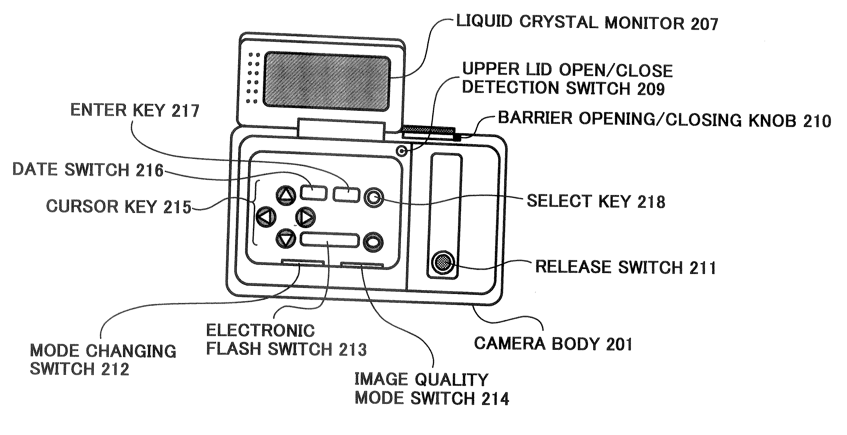
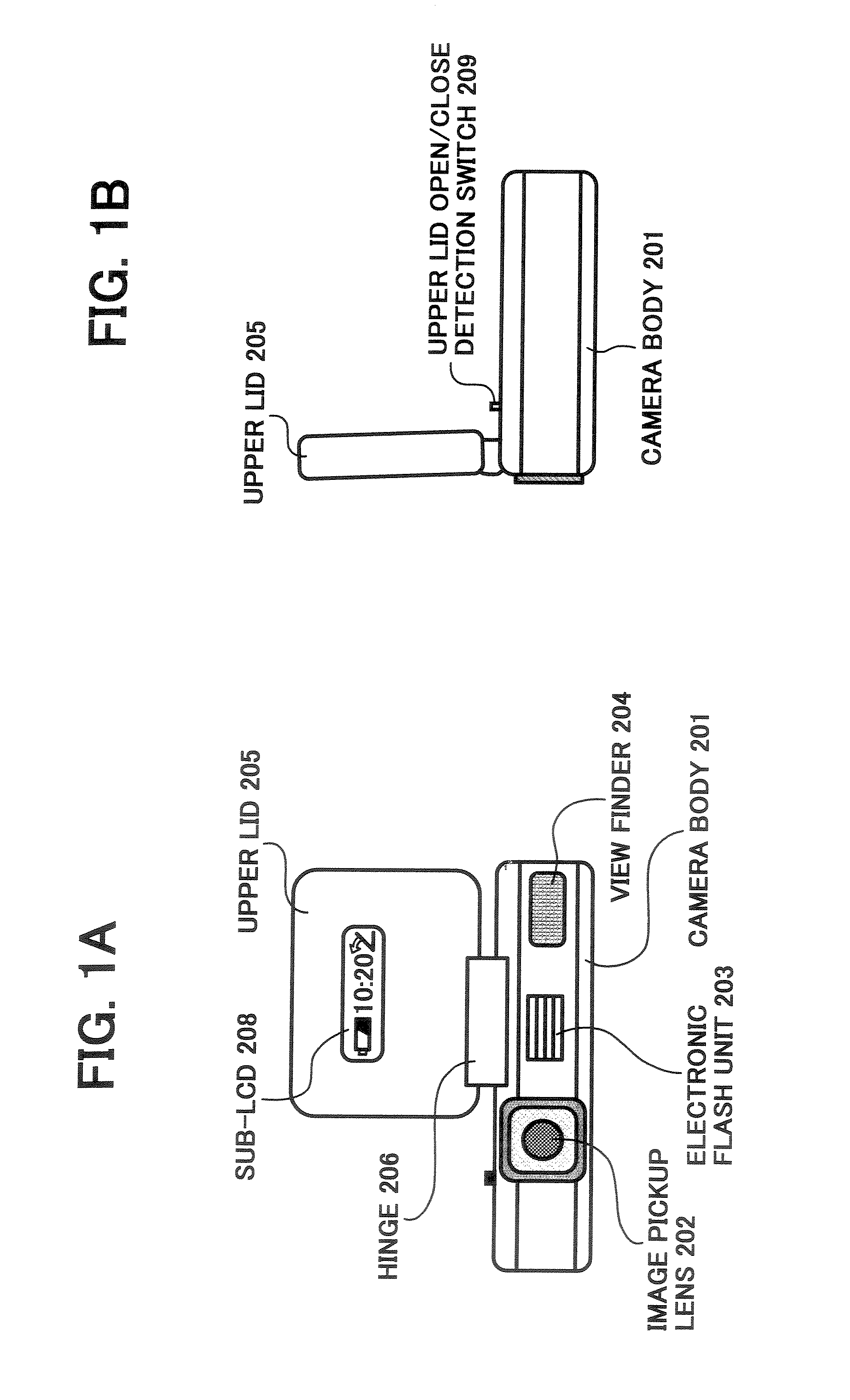
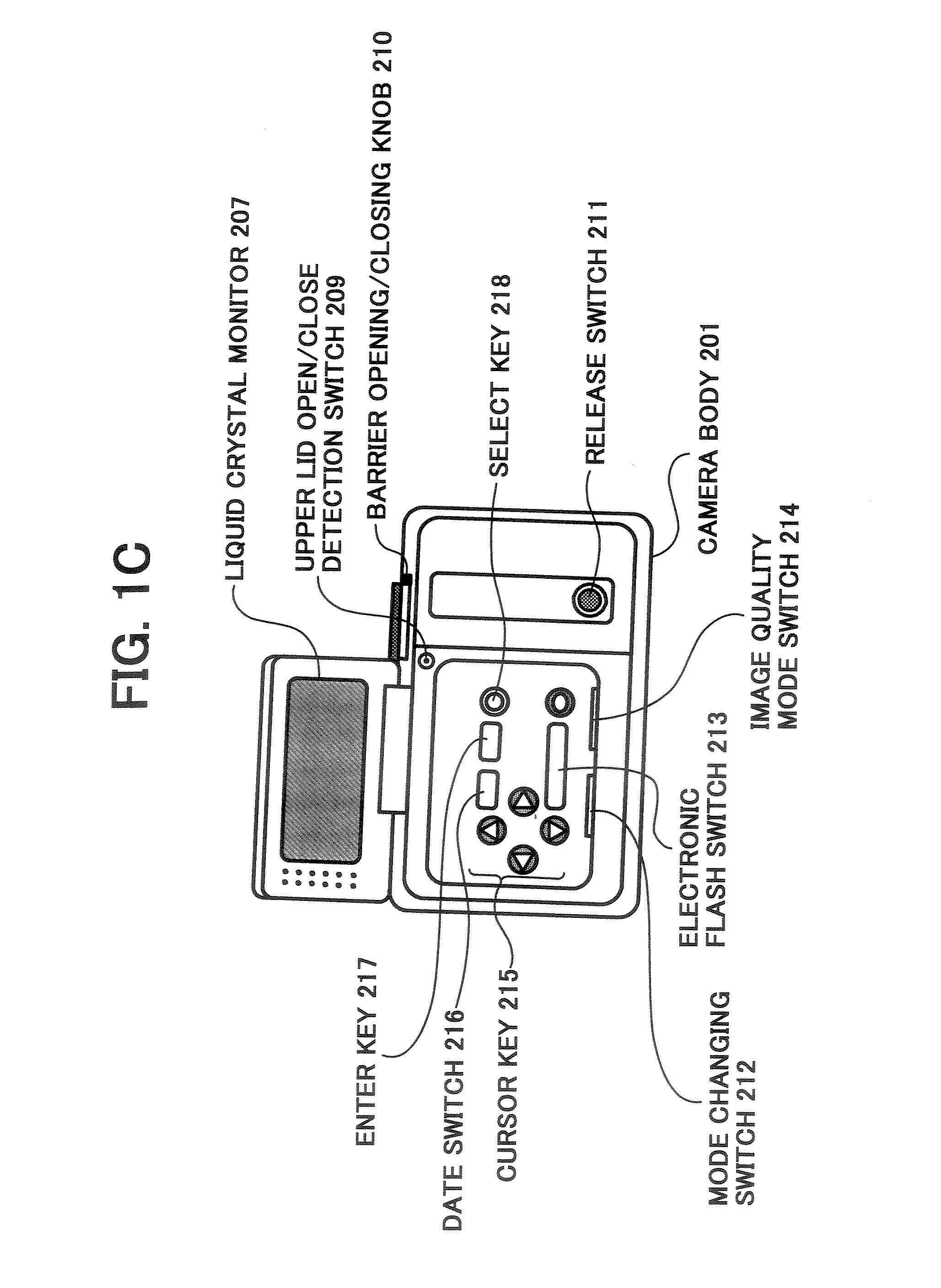
[0070]FIG. 1 is a block diagram which shows an appearance of a digital camera according to the first embodiment, in which FIG. 1A shows a front elevation, FIG. 1B shows a side view, and FIG. 1C shows a top view. FIG. 1 shows a state that an upper lid is opened. In this figure, reference number 201 denotes a camera body, 202 denotes an image pickup lens, 203 denotes an electronic flash unit, 204 denotes a viewfinder, 205 denotes the upper lid provided so as to be opened or closed, 206 denotes a hinge that supports the upper lid 205 so as to be opened or cl...

second embodiment

[0130] A digital camera according to a second embodiment will be explained, with reference to FIG. 2 and FIG. 10 to FIG. 19. In the second embodiment, a digital camera that can properly expose a human object, regardless of the position and range of the human object in the screen will be explained. The visual configuration and the block configuration of the digital camera according to the second embodiment are the same as those in the first embodiment (FIG. 1 and FIG. 2), and hence explanation of the common parts is omitted, and only the different part will be explained.

[0131]FIG. 10 andFIG. 11 show the user setup screen for recording conditions displayed on the liquid crystal monitor 207, when the SETUP mode is selected by the mode changing switch 212 in the operation section 108 in FIG. 2. The user setup screen for recording conditions shown in this figure is a screen for a user to set setting condition for each item ([AF / Manual] in “Focus”, [ON / OFF] in “Face detection (face detec...

first modification example

[0167] A human object photographing mode for taking a picture of a human object (first photographing mode) and a landscape photographing mode for taking a picture of landscape (second photographing mode) are provided in the digital camera of the present invention, such that the mode can be selected by, for example, the mode changing switch 212. When the human object photographing mode is selected, the CPU 115a performs exposure control accompanied with the face detection processing (processing after “YES” at step S1 in FIG. 14). When the landscape photographing mode is selected, the CPU 115a does not perform the face detection processing, and may perform the exposure control (processing after “NO” at step S1 in FIG. 14) by the normal photometric method. This is because, in the human object photographing mode in which it is necessary to properly expose the face, the face detection processing is necessary, but in the landscape photographing mode in which it is not necessary to properl...


PUM


Abstract

An image pickup device provided with an electronic flash function including an image pickup unit configured to input image data corresponding to a subject, a face detection unit configured to detect a human face from the image data input from the image pickup unit, an electronic flashing unit configured to emit electronic flash light, and an electronic flash control unit configured to control the electronic flashing unit based on the detection result of the human face by the face detection unit.

Description

CROSS-REFERENCE TO RELATED APPLICATIONS [0001] This application is a division of U.S. application Ser. No. 10 / 244,670, filed Sep. 17, 2002, and is based upon and claims the benefit of priority from prior Japanese Patent Application Nos. 2001-284162 filed Sep. 18, 2001, 2001-284163 filed Sep. 18, 2001, 2001-304342 filed Sep. 28, 2001, 2001-304343 filed Sep. 28, 2001, and 2001-304638 filed Sep. 28, 2001 the entire contents of each of which are incorporated herein by reference.BACKGROUND OF THE INVENTION [0002] 1) Field of the Invention [0003] The present invention relates to an image pickup device, an automatic focusing method, an automatic exposure method, an electronic flash control method and a computer program, which have a face detection function for detecting a face of a subject. [0004] 2) Description of the Related Art [0005] Recently, with a development of personal computers, use of digital cameras has become popular as image input devices thereof. Particularly, in many cases,...

Claims


Application Information

Patent Timeline
Patent Type & Authority Applications(United States)
IPC IPC(8): G06K9/46H04N5/232H04N5/235
CPCH04N5/23212H04N5/23219H04N5/23293H04N2101/00H04N5/2351H04N5/2354H04N5/235H04N23/675H04N23/61H04N23/611H04N23/632H04N23/635H04N23/70H04N23/71H04N23/74
Inventor OJIMA, NORIAKISHIRAISHI, KENJI
Owner RICOH KK
Learn More