System and method for non-lethal vehicle restraint

a non-lethal and vehicle technology, applied in roadway safety arrangements, roads, construction, etc., can solve the problems of time-consuming and labor-intensive vehicle stop, inconvenient installation, and inability to carry barriers

Active Publication Date: 2007-11-15
ENG SCI ANALYSIS
View PDF31 Cites 53 Cited by
  • Summary
  • Abstract
  • Description
  • Claims
  • Application Information

AI Technical Summary

Benefits of technology

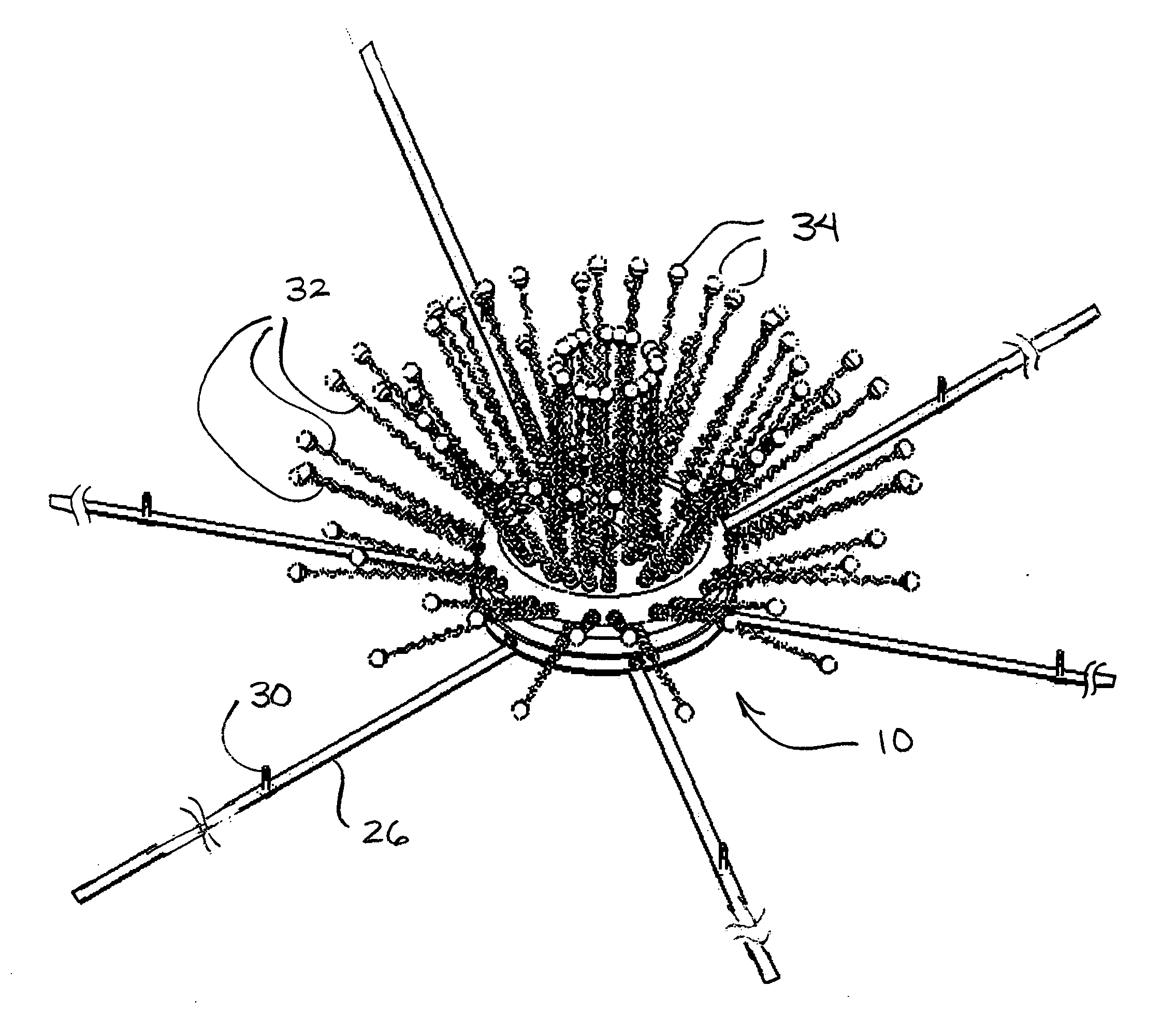
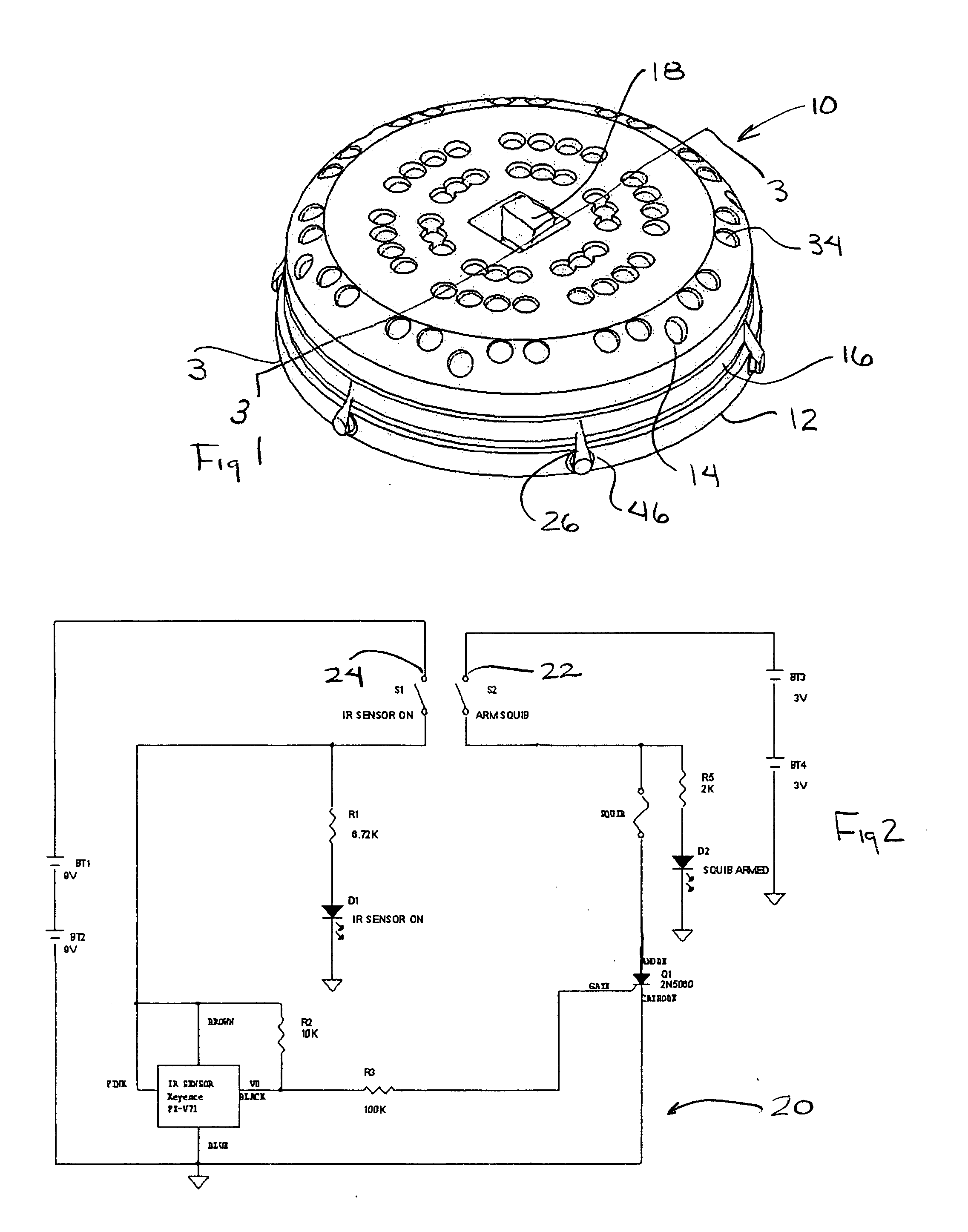
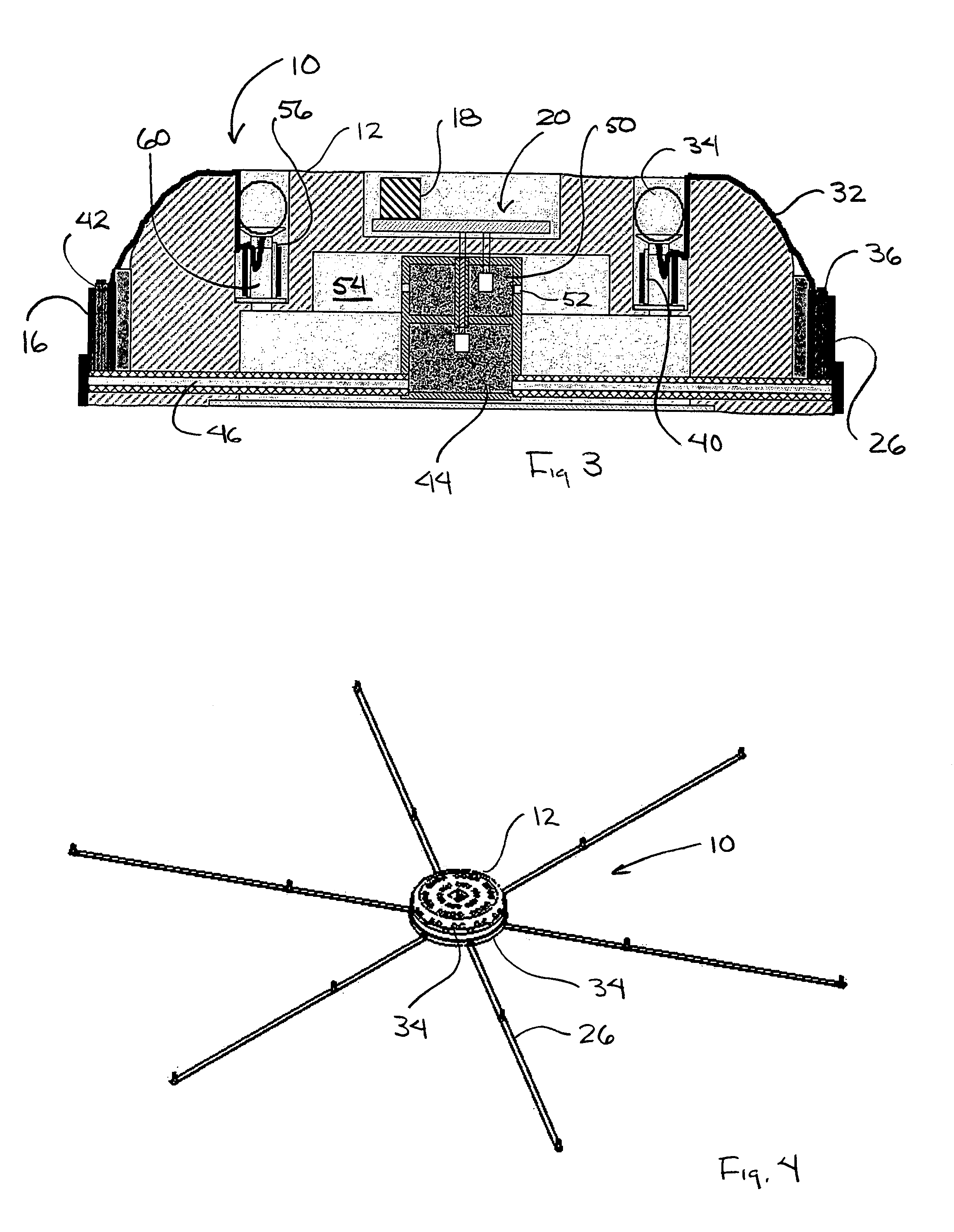
[0019] The undercarriage immobilization device presented here is a small, compact, lightweight and inexpensive undercarriage immobilization device that can be readily deployed by ground-based personnel from a moving vehicle or from aircraft. The undercarriage immobilization device is capable of slowing and eventually stopping a vehicle by ensnaring the rotating components on the underside of the vehicle and rendering these components immobile. Once positioned in the expected path of a target vehicle the undercarriage immobilization device is prepared for a two-event activation cycle by safely arming the device remotely either through a proximity sensor, a RF remote activator, or through a hard-wired controller. After arming the device the first event is activated to deploy a plurality of inflatable primary straps and at this point the undercarriage immobilization device is ready for interaction with a target vehicle.
[0039] One advantage of this invention is that the undercarriage immobilization device does not rely on stopping the vehicle by completely ensnaring it, as it would be if a net were used as the restraining device. Rather the undercarriage immobilization device is capable of stopping a vehicle by ensnaring the rotating components beneath the vehicle and rendering them immobile.

Problems solved by technology

Once tire contact is made with the spike strip it will cause deflation of vehicle tires, and eventually cause the vehicle to stop due to the vehicle being difficult to control on flat tires.
Barriers, such as concrete barricades, can be effective but to set them up is time consuming and barriers are not particularly portable.
Snares, such as a net that is stretched across a road, can also be effective in stopping a vehicle but such snares are time consuming to set up, are generally bulky and heavy and need to be anchored securely to restrain a moving vehicle.
Such electrical based-disabling devices may have limited or no effect on vehicles with shielded electrical systems or on vehicles that are not electronically dependent to operate.

Method used


Image

  • System and method for non-lethal vehicle restraint
  • System and method for non-lethal vehicle restraint
  • System and method for non-lethal vehicle restraint

Examples


Embodiment Construction

[0057] In the following description, and for the purposes of explanation, numerous specific details are set forth in order to provide a thorough understanding of the various aspects of the invention. It will be understood, however, by those skilled in the relevant arts, that the present invention may be practiced without these specific details. In other instances, known structures and devices are shown or discussed more generally in order to avoid obscuring the invention. In many cases, a description of the operation is sufficient to enable one to implement the various forms of the invention, particularly when the operation is to be implemented in software. It should be noted that there are many different and alternative configurations, devices and technologies to which the disclosed inventions may be applied. The full scope of the invention is not limited to the examples that are described below.

[0058] In one application of the invention the non-lethal restraint or undercarriage i...


PUM


Abstract

An undercarriage immobilization device and method of restraining a vehicle uses tendrils and straps to engage the vehicle. The tendrils and straps will wrap around moving parts of the vehicle and restrain the moving parts to eventually incapacitate the vehicle. The undercarriage immobilization device includes a housing that contains tendrils that are launched from the housing by a propellant or compressed gas. The tendrils may be attached to the straps carried by the undercarriage immobilization device. Straps may be pulled off the housing leaving the housing near the point of deployment.

Description

CROSS REFERENCE TO RELATED APPLICATION [0001] This application is entitled to the benefit of previously filed Provisional Patent Application No. 60 / 775,495, filed Feb. 21, 2006, herein incorporated in its entirety.STATEMENT REGARDING FEDERALLY SPONSORED RESEARCH [0002] Some elements of this invention were developed under Department of Homeland Security SBIR Contract NBCH060024.BACKGROUND OF THE INVENTION [0003] 1. Field of the Invention [0004] This invention is related to a system, apparatus and method for the non-lethal restraint of a vehicle through the use of an entanglement device that will entangle such vehicle. The non-lethal entanglement device incorporates a plurality of tendrils, filaments, tentacles or straps, or a combination there of, that are propelled from a housing by compressed gas or by pressure generated by a gas generator of the type commonly used in air bag deployment apparatus. Filaments that are launched from the device may be attached to frangible balls carryi...

Claims


Application Information

Patent Timeline
Patent Type & Authority Applications(United States)
IPC IPC(8): E01F13/12
CPCE01F13/12F42B23/04F41H13/0006F41H11/08
Inventor MARTINEZ, MARTIN A.BARNHILL, PATRICK J.FLOYD, STEVEN A.
Owner ENG SCI ANALYSIS
Why Eureka
Try Eureka