Vascular coagulation forceps

a technology of coagulation forceps and clamps, applied in the field of vascular coagulation forceps or clamps, can solve problems such as uncertainties in methods, and achieve the effect of increasing measurement accuracy

Inactive Publication Date: 2007-11-15
OLYMPUS WINTER & IBE
View PDF2 Cites 190 Cited by
  • Summary
  • Abstract
  • Description
  • Claims
  • Application Information

AI Technical Summary

Benefits of technology

[0010]To increase accuracy of measurement, the coil axis should run through the zone of coagulation. This goal is attained by the the coil unit being configured parallel to the gripping surface of a jaw. The coil unit is configured inside the active surface of a forceps jaw, thereby meeting th

Problems solved by technology

This method however e

Method used


Image

  • Vascular coagulation forceps
  • Vascular coagulation forceps

Examples


Embodiment Construction

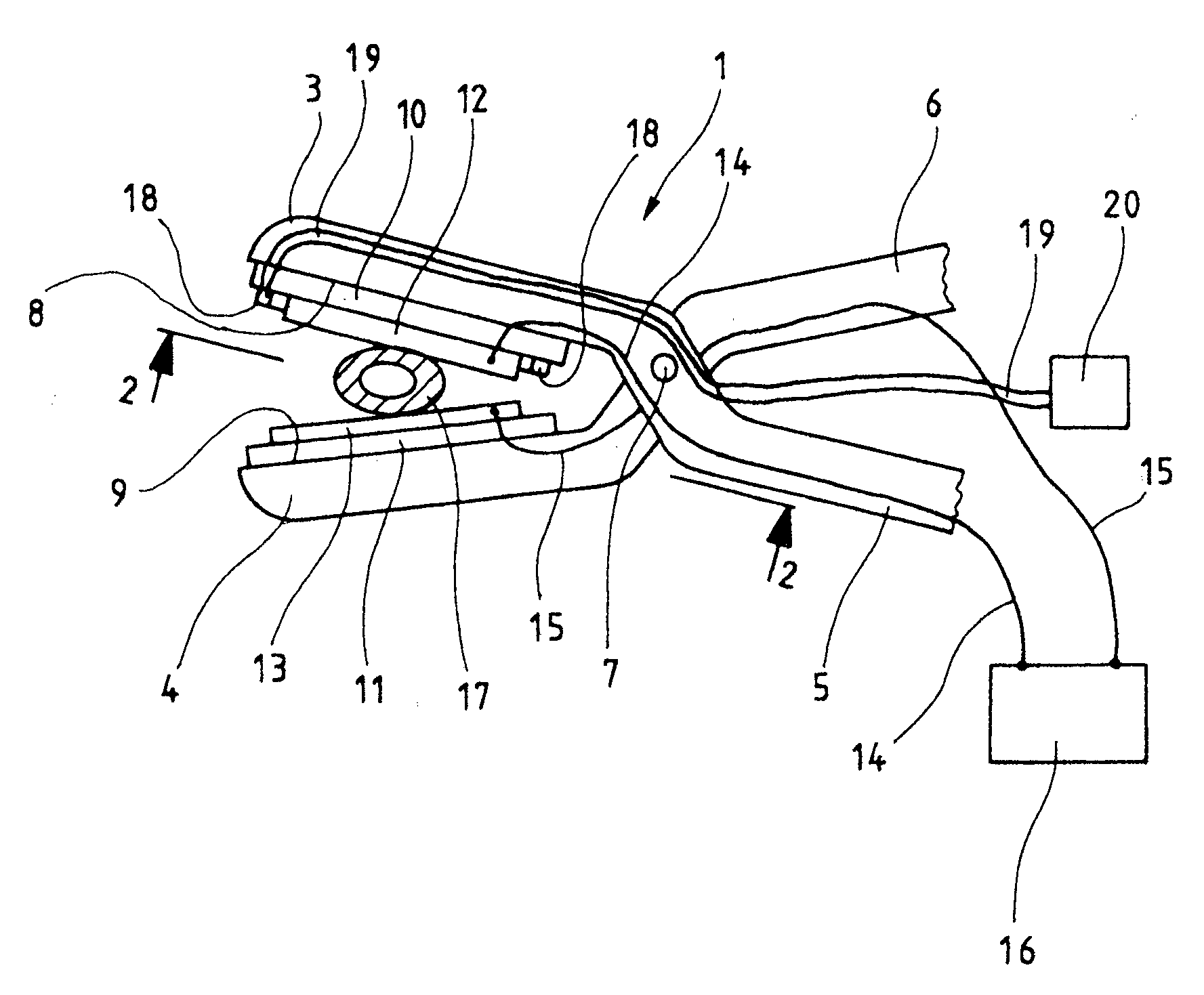
[0015]In a much simplified embodiment mode, the Figures show a bipolar forceps 1 with two jaws 3, 4 which extend proximally into handles 5, 6 and are articulating with each other by a pivot pin 7. The forceps also may be designed with another kind of pivot, to form a laparoscopic stem forceps while retaining essentially the same jaws 3, 4.

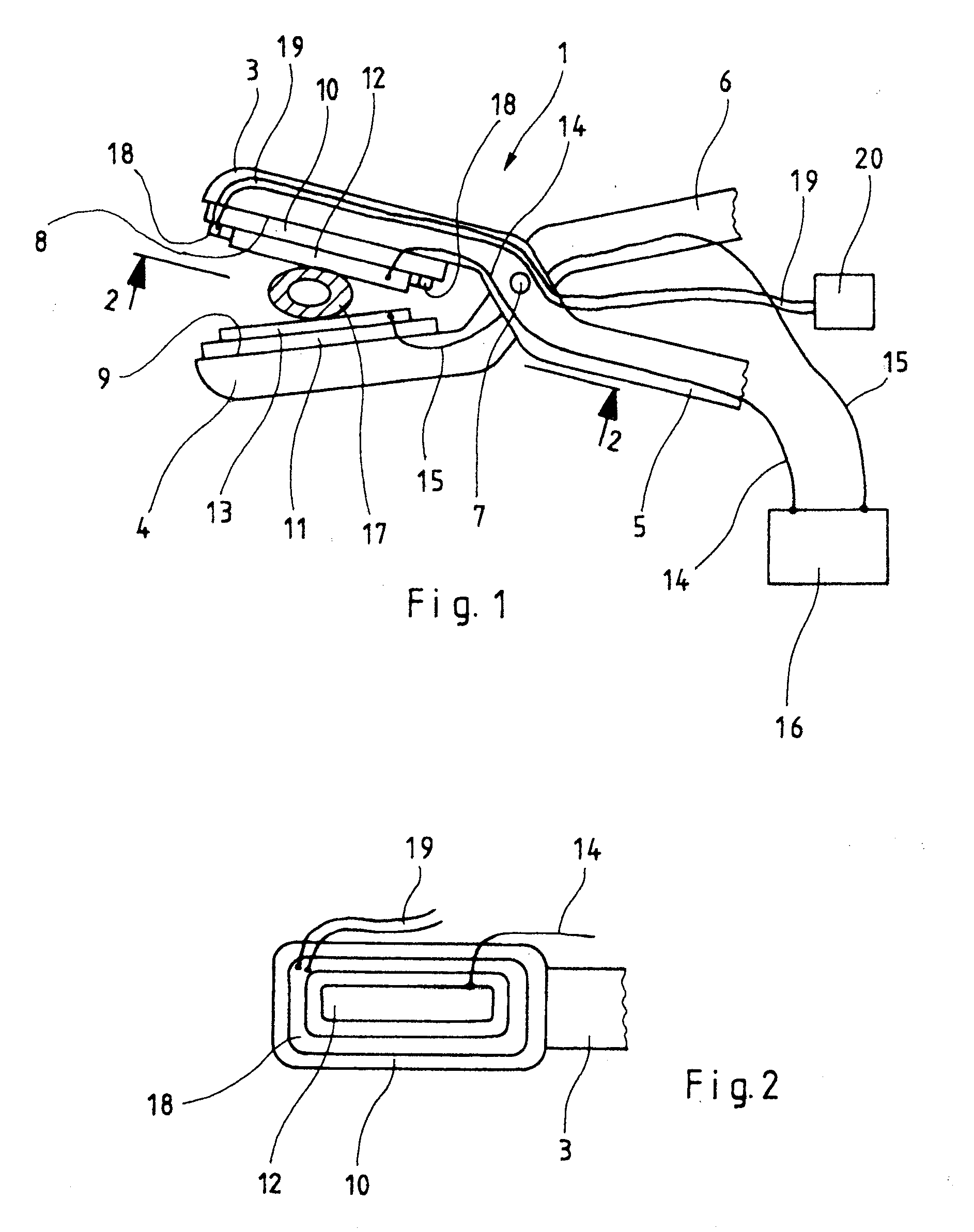
[0016]The two forceps elements 3, 5 and 4, 6 shown in the present embodiment are entirely metallic. Electrically insulating plates 10, 11 rest on the engaging surfaces 8, 9 that are displaced toward each other when the forceps 1 is closing and in turn support metal electrode plates 12, 13 connected by electrical conductors 14, 15, installed at the jaws 3,4 and the handles 5, 6, to the two terminals of a high frequency source 16.

[0017]As shown in FIG. 1, the bipolar forceps 1 is used to seal a blood vessel, for instance an artery 17 shown sectionally in FIG. 1. As further shown in FIG. 1, the artery is seized between and squeezed by the jaws 3, 4 of...


PUM


Abstract

A surgical, vascular coagulation forceps (1) comprising two mutually displaceable jaws (3, 4) bearing flat electrodes (12, 13) connected to different terminals of an hf source (16), or one of said jaws being fitted with an ultrasonic oscillator, characterized in that a coil unit (18) connected to an eddy current sensor (20) is mounted on at least one of the jaws (3, 4).

Description

BACKGROUND OF THE INVENTION[0001]The present invention relates to a vascular coagulation forceps or clamp including two mutually displaceable jaws bearing flat electrodes.[0002]Such forceps are used in surgery to grip between their jaws blood vessels to be severed to squeeze them into a closed position and to heat them in said position by applying ultrasonics to or an hf current through them, the tissue coagulating thereby and hence sealing the blood vessel. Thereupon, using a cutter on the forceps or separate scissors, the blood vessel can be severed at its coagulated site.[0003]High requirements apply to such coagulation. The thermal tissue coagulation must have advanced enough to reliably seal the blood vessel, for instance, and also to reliably seal the blood vessel which, for instance, also should withstand high arterial pressure. Accordingly, reliable bonding must be attained while ensuring that tissue strength be retained even if its coagulation should be excessive.[0004]Conv...

Claims


Application Information

Patent Timeline
IPC IPC(8): A61B18/14
CPCA61B17/320092A61B2017/00026A61B18/1442A61B2017/320094A61B2017/320095
Inventor KRAAS, MATHIASMUCKNER, ANDREASKLOCKNER, STEPHAN
Owner OLYMPUS WINTER & IBE
Why Eureka
Try Eureka