Eureka AIR delivers breakthrough ideas for toughest innovation challenges, trusted by R&D personnel around the world.

Quick release connector for dual-sided buffing pad

Inactive Publication Date: 2007-11-22
UMBRELL RICHARD T
View PDF17 Cites 14 Cited by
  • Summary
  • Abstract
  • Description
  • Claims
  • Application Information

AI Technical Summary

Benefits of technology

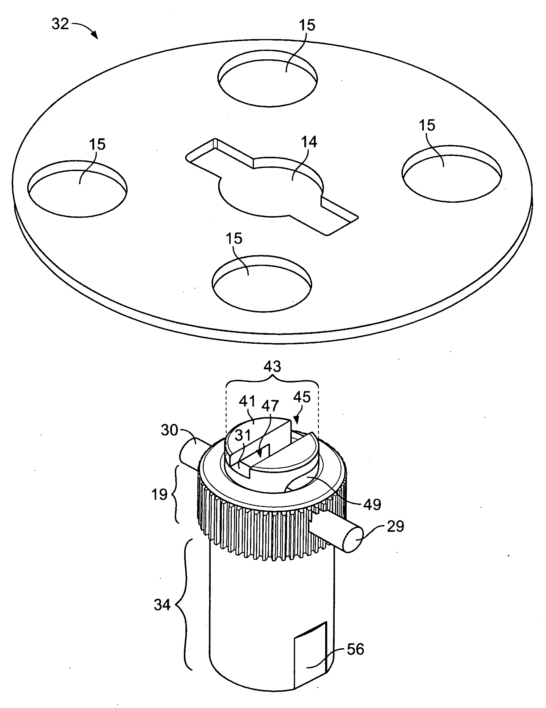
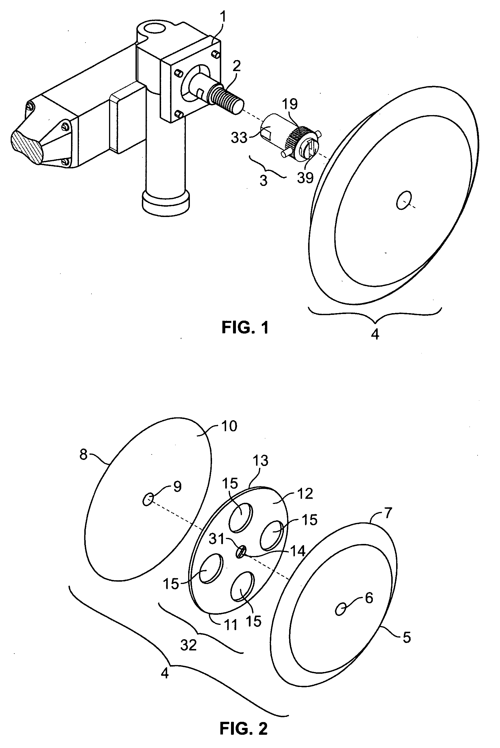
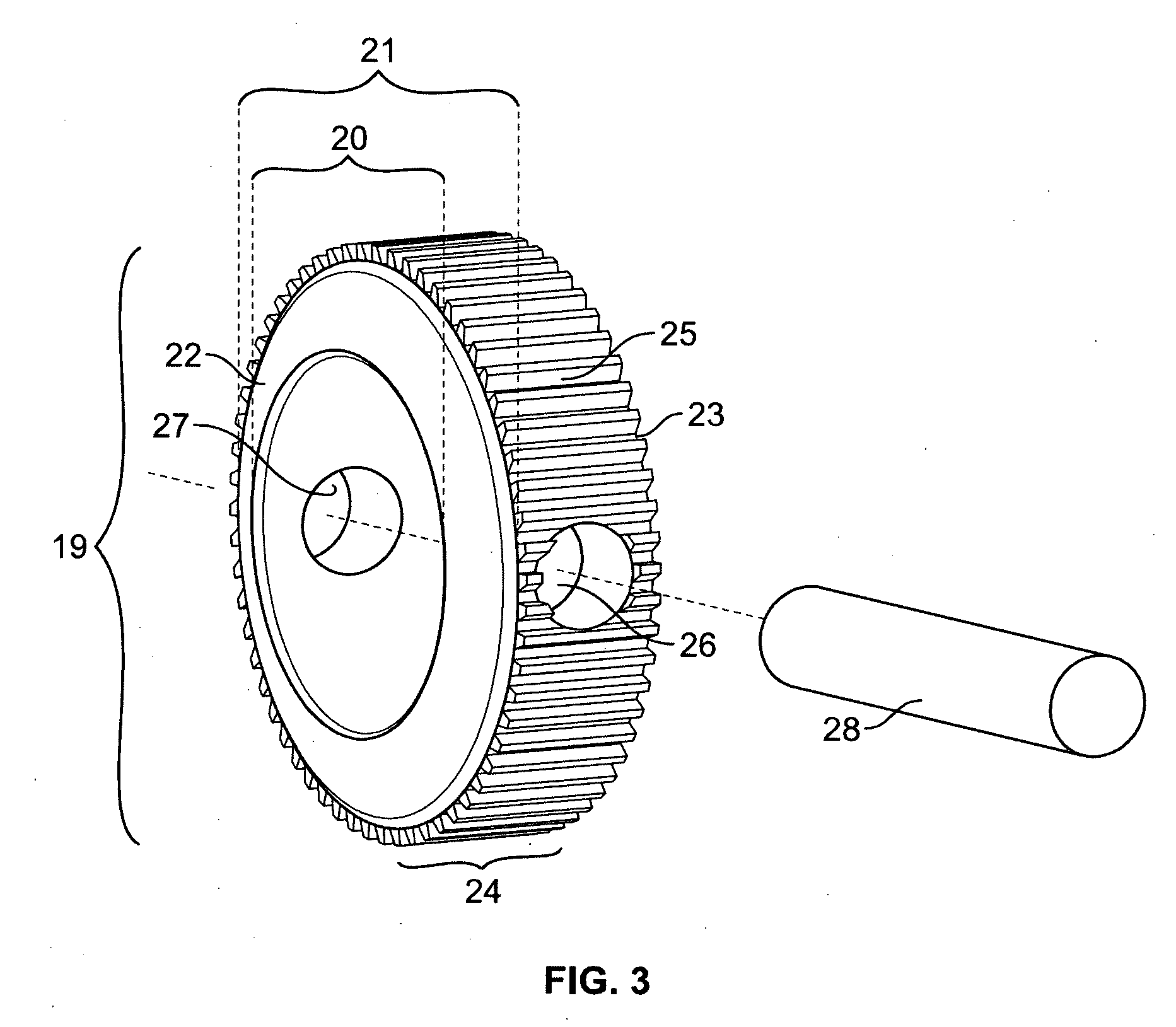
[0018]The present invention provides a quick release mechanism for a dual-sided buffing pad assembly that overcomes the aforementioned drawbacks of the prior art. The quick release mechanism includes a connector that enables a dual-sided buffing pad assembly to be quickly and easily engaged and disengaged from the spindle of a power buffer. The quick release connector further includes a circular connector head that engages a corresponding circular socket in the center of the dual-sided buffing pad, thereby simplifying alignment between the connector and socket. The quick release connector includes no moving internal mechanical parts that can become fouled by contact with buffing compound or that can wear out from normal use.

Problems solved by technology

The continuous revolutions of either type of buffer causes friction on contact with the surface producing heat, that when combined with a compound alters the surface of the automobile.
If any one of these fail, the results will be less than desirable.
An uneven application of the compound can cause unsightly swirls on the surface that can only be removed by a polisher and not by hand, if at all.
An uneven application or a faulty assembly can cause the wool pad to chip away at the surface and cause more damage.
Also, dual-sided pads do not have an exposed backing plate that may contact the automobile surface and cause damage.
A drawback of this approach is that it is time consuming and cumbersome to change buffing pads during use.
Another drawback is that this approach cannot be used with double-sided buffing pads.
As with the bolt-on method, the hook and loop fastening method cannot be used with double-sided buffing pads.
A drawback of this method is that the high speed rotation of the spindle tends to further tighten the male end of the adapter onto the buffing pad, making it difficult to manually remove the buffing pad from the adapter.
Another drawback is that the plastic plate with the double-sided pad is necessarily disposed of when both sides of the pad are spent, thereby increasing the replacement cost of the buffing pad.
Notwithstanding the advantages of the known quick release mechanism, there are also many practical drawbacks.
Since the connector body is typically formed of a high strength material, such as metal, the hexagonal shaped head is difficult and hence expensive to manufacture, particularly in comparison to a simple, round head.
Moreover, it is difficult to align the hexagonal connector head onto the corresponding hexagonal socket.
The buffing pad impedes a clear view of the socket and the operator will typically fumble with the device for a while before getting the connector head and socket aligned together.
After continued use, the plastic socket at the center of the backing plate tends to wear out, providing an even looser fit with the hexagonal shaped head.
If the connector head does not maintain a snug fit with the socket, the buffing pad will wobble during operation.
This causes an undesirable vibration that effects the rotation of the buffing pad, thereby causing poor application of the compound.
The vibration also contributes to operator fatigue, and thereby reduces the productivity of the automotive detailing operation.
This exerts force on the buffing pad assembly that could cause it to inadvertently pop off of the connector during use, potentially resulting in injury to the operator and / or damage to the automobile surface.
To avoid this condition, the operator may be tempted to increase the tension on the internal spring by tightening the adjusting screw in order to thereby achieve a tighter fit; however, this makes it more difficult to use the quick release mechanism to remove the buffing pad when it is spent.
Another drawback with the known quick release mechanism is that the compound used to buff the surface tends to collect in the socket at the center of the plate.
The compound gets into the body of the connector and impedes retraction of the protruding balls.
As a result, it becomes difficult to remove the buffing pad assembly from the connector.
Even under normal conditions without the presence of compound in the body of the connector, the factory setting of the spring tension applied by the release mechanism can require significant pressure by the operator to overcome and thereby compress the spring.
Yet another drawback of the known quick release mechanism is that the connector body is relatively long in comparison to the traditional adapter due to the inclusion of the release mechanism within the body of the connector.
This relatively longer distance between the buffer and the pad can be disorienting for the operator that is already accustomed to a certain shorter distance.
This tends to further exacerbate operator fatigue and result in an uneven application to the automotive surface.

Method used


Image

  • Quick release connector for dual-sided buffing pad
  • Quick release connector for dual-sided buffing pad
  • Quick release connector for dual-sided buffing pad

Examples


Embodiment Construction

[0041]The present invention provides a quick release assembly that is used to connect a dual-sided buffing pad assembly to the spindle of a power buffer. The present invention satisfies the need for a quick release mechanism that fits securely at the center of the dual-sided buffing pad assembly without interfering with the overall function of the power buffer, while being convenient and easy to attach and remove the buffing pad assembly from the power buffer. In the detailed description that follows, like element numerals are used to describe like elements shown in one or more of the figures.

[0042]FIG. 1 provides an exploded view of a power buffer 1, a dual-sided buffing pad assembly 4, and a quick release assembly 3. The power buffer 1 includes a handle that is carried by an operator and used to hold the buffer and buffing pad assembly in relation to a surface. The body of the power buffer 1 includes a motor that rotatably drives a spindle 2. The power buffer 1 will typically incl...


PUM

PropertyMeasurementUnit
Angleaaaaaaaaaa
Magnetic fieldaaaaaaaaaa

Abstract

A quick release attachment for a power buffer having a rotatable spindle includes a buffing pad assembly and a quick release connector adapted to join the buffing pad assembly to the spindle. The buffing pad assembly includes a mounting plate and a buffing pad affixed to either side of the mounting plate. The mounting plate and the buffing pads each have respective aligned central apertures. The mounting plate aperture further comprises a circular ring disposed therein and has a pin extending diametrically across the aperture. The pin comprises a magnetically attractive material. The quick release connector has a main body adapted to fixedly engage the spindle. The connector further has a head end extending from the main body and having a circular cross-section sized to engage the circular ring. The head end further has a slot sized to engage the pin. The slot further comprises a distal portion extending axially along the head end, a proximal portion extending axially along the head end offset from the distal portion, and a transition portion joining the distal and proximal portions. The main body further comprises a permanent magnet disposed therein having at least one surface adjacent to the proximal portion of the slot. The buffing pad is selectively affixed to the quick release connector by manipulating the head end into the aperture and moving the pin through the slot until reaching the proximal portion, whereupon the pin is retained by the magnetic attraction of the permanent magnet.

Description

BACKGROUND OF THE INVENTION[0001]1. Field of the Invention[0002]The present invention is directed towards power buffing equipment for automobile body refinishing, and more particularly, to a quick release connector used to connect a dual-sided buffing pad assembly to a power buffer or polisher.[0003]2. Description of Related Art[0004]Buffing refers to the application of a chemical or compound to a surface using a buffing pad. In the automotive detailing industry, for example, buffing is used to repair, refinish or polish the exterior surfaces of automobiles. Buffing can be done by hand, however, professionals and consumers alike prefer to use buffing pads with power buffers. A power buffer can be pneumatic, in which the power is supplied by an air compressor, or motorized, in which the power is supplied by an electric motor. A motorized power buffer is a hand-held tool having a buffing pad attached to a spindle that extends from the electric motor. The motor spins the buffing pad an...

Claims


Application Information

Patent Timeline
IPC IPC(8): B24D13/08
CPCB24B45/006B24D13/20Y10T403/7005Y10T279/17888Y10T403/7007Y10T83/9379
Inventor UMBRELL, RICHARD T.
Owner UMBRELL RICHARD T
Why Eureka
Eureka Blog
Learn More