Cyclone separator with fine particle separation member
a technology of cyclone separator and separator, which is applied in the direction of auxillary pretreatment, cleaning filter means, separation processes, etc., can solve the problems of not being able to pass through the apertured particle separation member into the dead zone, fine particles are not separated from in the airstream, and end up in the downstream filter
- Summary
- Abstract
- Description
- Claims
- Application Information
AI Technical Summary
Benefits of technology
Problems solved by technology
Method used
Image
Examples
first embodiment
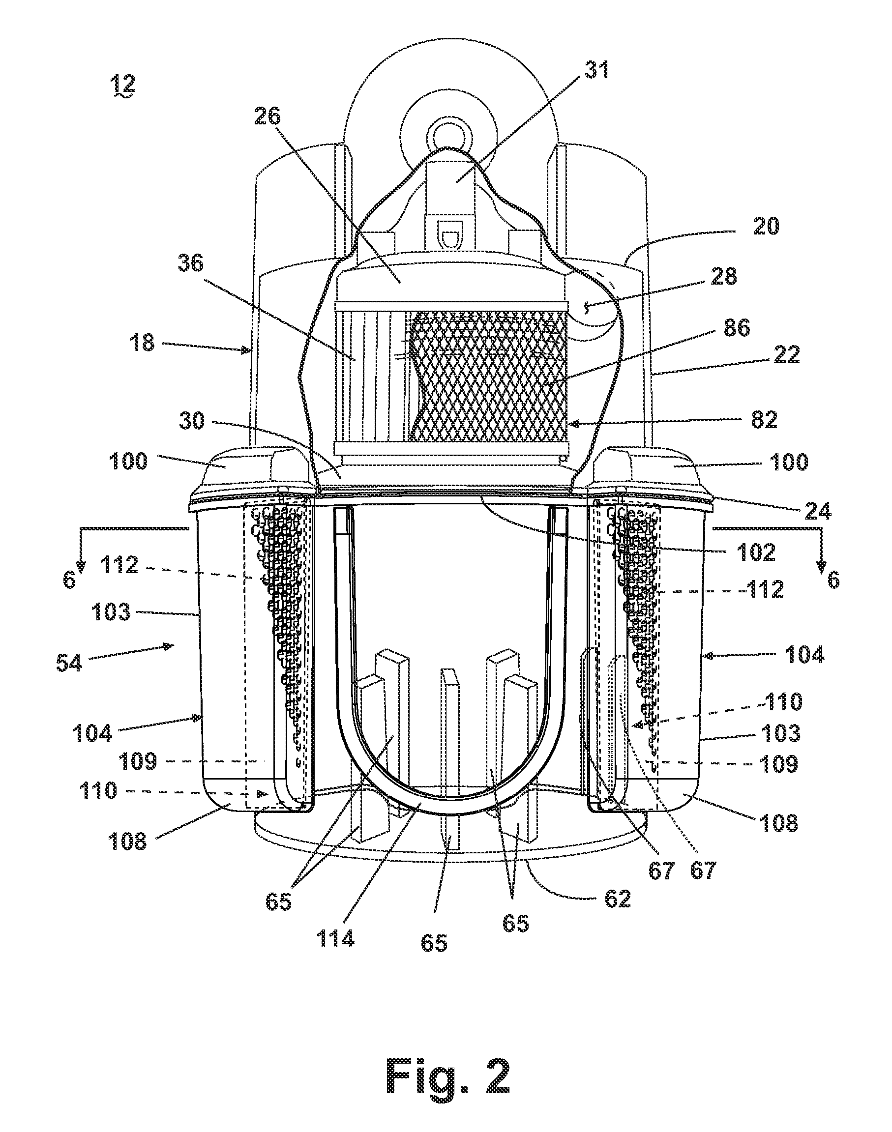
[0076] During operation, a working airstream enters and flows through the cyclone separation assembly 12 as described above with respect to the first embodiment cyclone separation assembly 12 in FIGS. 1-6; however, fine particles are separated from the airstream in the cyclone separator 18 through the upper fine particle separation members 110A as well as in the dirt cup 54 through the lower fine particle separation members 110B. The fine debris that passes through the upper fine particle separation member 110A enters the upper fine particle collection chamber 101A and falls into the lower fine particle collection chamber 110B, and the fine debris that passes through the lower fine particle separation member 110B enters the lower fine particle collection chamber 101B. Thus, the fine debris, whether separated in the cyclone separator 18 or the dirt cup 54 falls under force of gravity to the closed bottom 108 of the fine particle collectors 104. Debris in the fine particle collectors ...
fifth embodiment
[0080] Like the fifth embodiment illustrated in FIG. 13, each fine particle collector 104 comprises an open-bottom upper fine particle collection chamber 101A adjacent the cyclone separator sidewall 22 and an open-top lower fine particle collection chamber 101B adjacent the dirt cup sidewall 64 and the fine particle separation member 110, which forms an effectively continuous side wall with the separator sidewall 22. Alternately, the fine particle separation member 110 can be formed integrally with the side wall 22. The upper and lower fine particle collection chambers 101A, 101B are joined to form a single fine particle collection chamber 101 when the dirt cup 54 is mounted beneath the cyclone separator 18, as shown in FIG. 20. Alternately, the fine particle collectors 104 can span only the cyclone separator 18.
[0081] The cyclone separator 18 further comprises a separation wall 124 formed in spaced relation to the top wall 20, thereby forming a lower wall of a outlet chamber 126 in...
seventh embodiment
[0087] While not shown, it is understood that the cyclone separator 18 can comprise a filter assembly, similar to the filter assembly 82 shown in FIGS. 1-6, or a frustoconical separator, similar to the frustoconical separators 18 shown in FIGS. 10-12, and the dirt cup 54 can comprise a plurality of finger-like projections extending vertically from the bottom wall 62 of the dirt cup 54, similar to the projections 65 shown in FIGS. 1-6.
[0088] During operation, the working airstream enters the tangential air inlet 28 and flows in a cyclonic fashion around the sidewall 22. As the air circulates, larger particles entrained in the airstream are separated therefrom and fall to the bottom of the dirt cup 54. The airstream remains entrained with fine particles and passes into the outlet chamber 126 through the outlet chamber inlet 128. In the outlet chamber 126, the airstream encounters the guide plate 122, which forces the airstream, in sequence, radially outwardly, vertically, and radially...
PUM
| Property | Measurement | Unit |
|---|---|---|
| inertia | aaaaa | aaaaa |
| speed | aaaaa | aaaaa |
| centrifugal force | aaaaa | aaaaa |
Abstract
Description
Claims
Application Information
 - R&D
- Intellectual Property
- Life Sciences
- Materials
- Tech Scout
- Unparalleled Data Quality
- Higher Quality Content
- 60% Fewer Hallucinations
Browse by: Latest US Patents, China's latest patents, Technical Efficacy Thesaurus, Application Domain, Technology Topic, Popular Technical Reports.
© 2025 PatSnap. All rights reserved.Legal|Privacy policy|Modern Slavery Act Transparency Statement|Sitemap|About US| Contact US: help@patsnap.com


