Camera and lens unit

a technology which is applied in the field of lens unit and camera body, can solve the problems of confined use of camera body without lens unit, and the grip is not always optimal for any kind of interchangeable lens unit, and achieve the effect of optimal gripping

Inactive Publication Date: 2007-11-22
FUJIFILM CORP
View PDF8 Cites 74 Cited by
  • Summary
  • Abstract
  • Description
  • Claims
  • Application Information

AI Technical Summary

Benefits of technology

[0005] In view of the foregoing, a primary object of the present invention is to provide a camera that widens the range of usage of a second unit having an image recording function.
[0006] Another object of the present invention is to provide a camera that ensures stable gripping with any kind of a first unit having an imaging section.

Problems solved by technology

However, since the prior lens-interchangeable digital camera is simply divided into the lens unit served as an imaging section and the camera body served as an image processing, recording and displaying section, the usage of the camera body without the lens unit is confined.
Also because a grip of the prior lens-interchangeable digital camera is integrally formed with the camera body, the grip is not always optimum for any kinds of interchangeable lens units whose size and shape are variable.

Method used


Image

  • Camera and lens unit
  • Camera and lens unit
  • Camera and lens unit

Examples


first embodiment

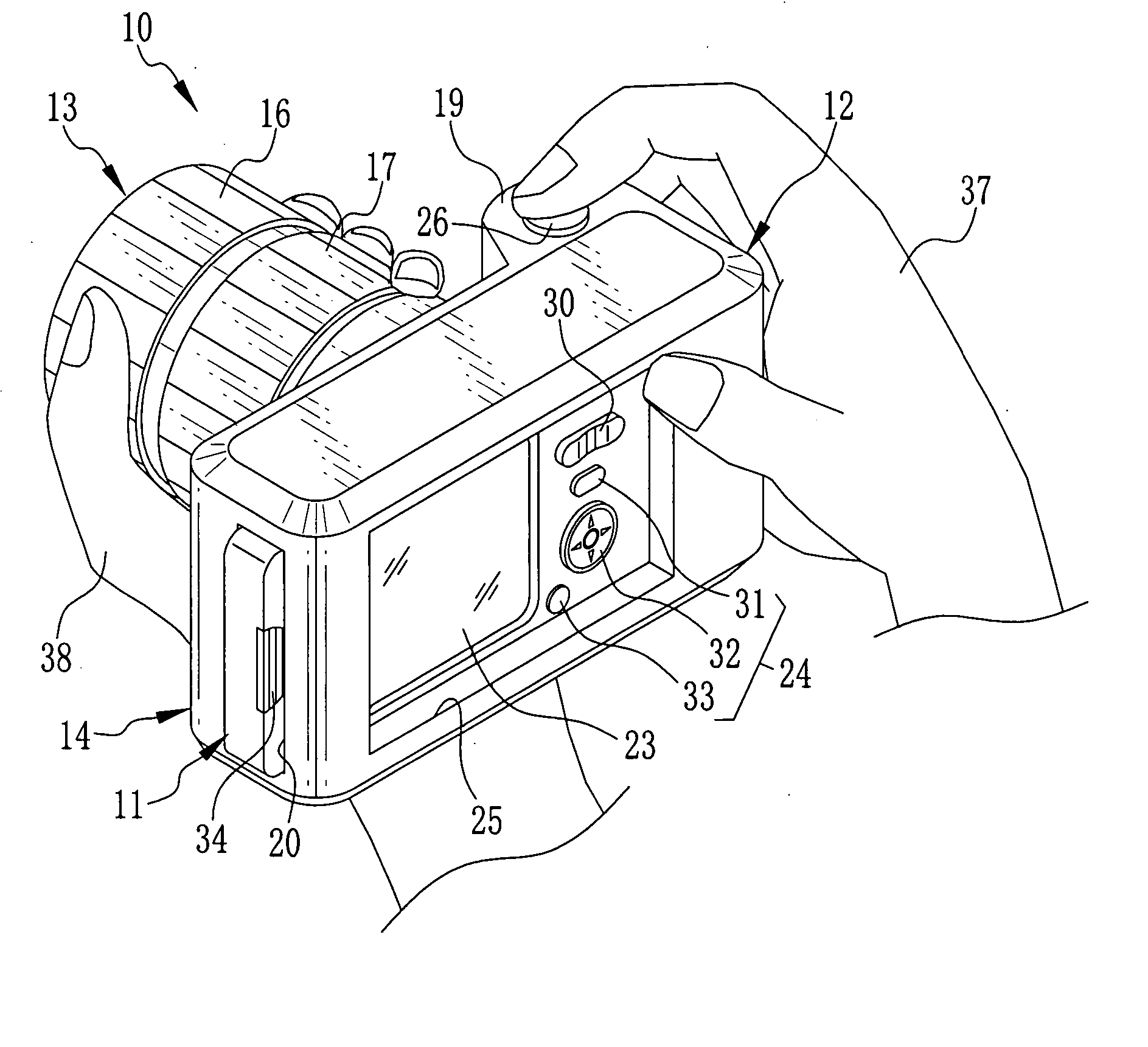
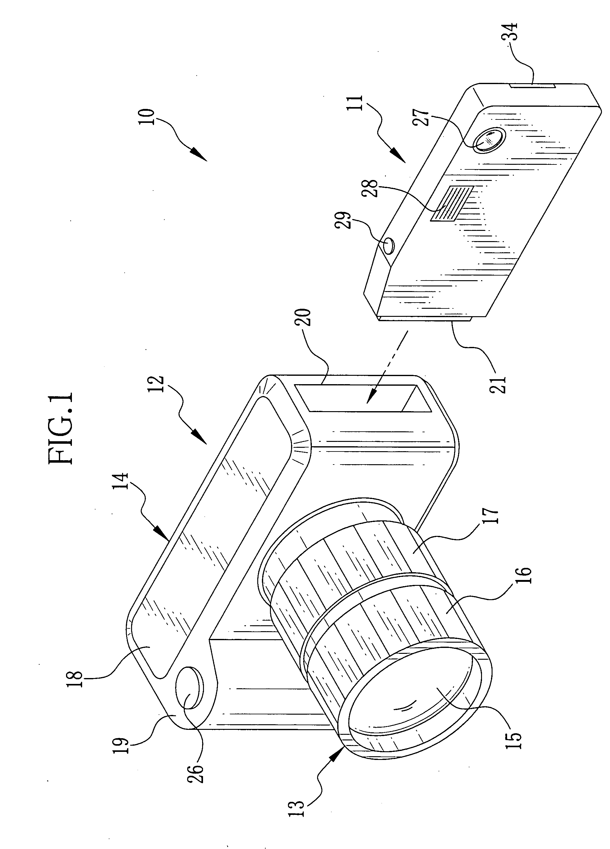
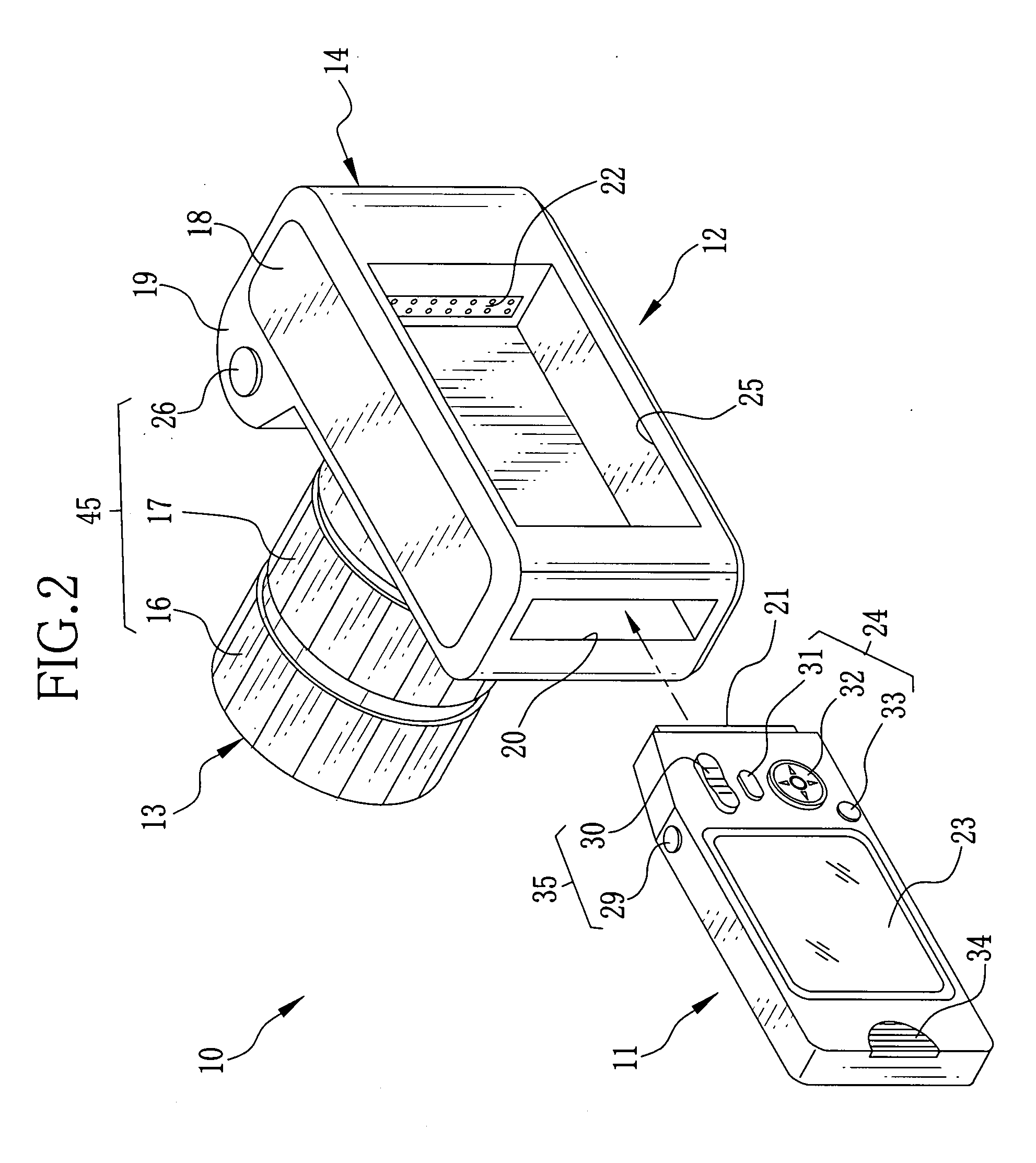
[0047] In FIGS. 1 and 2, a camera 10 consists of a first unit 12 (lens unit) and a second unit 11 (camera body) detachably attachable to the first unit 12. The first unit 12 consists of a cylindrical lens barrel 13 having an optical system 40 and an imaging device 44 mounted therein, see FIG. 3, and a base body 14 affixed to the lens barrel 13.

[0048] The lens system is superior in optical performance (for example, aberration, resolution, and open f number). The imaging device 44 has many pixels, so use of the first unit 12 allows the user to capture high-quality images.

[0049] A taking lens 15 of the optical system 40 is exposed on a front face of the lens barrel 13, and a rear end of the lens barrel 13 is connected to the base body 14. A focusing ring 16 and a zooming ring 17 are mounted on a peripheral surface of the lens barrel 13. The focusing ring 16 permits manual focusing by the user, whereas the zooming ring 17 permits manual zooming by the user.

[0050] The base body 14 con...

second embodiment

[0081]FIGS. 8 and 9 show a camera 70 of the second embodiment that consists of a first unit 72 and a second unit 71. On a rear side portion of a base body 14 of the first unit 72, there is provided the same operating section 76 as the operating section 24 of the second unit 71. The operating section 76 consists of a menu button 73, a cursor button 74 and a power button 75, and enables operating the second unit 71 from the first unit 72.

[0082] As shown in FIG. 9, a switching circuit 77 is fed with operational signals from the operating section 24 and an operating section 35 of the second unit 71, or ones from the operating section 76 and an operating section 45 of the first unit 72. The operating section 45 consists of a focusing ring 16, a zooming ring 17 and a shutter button 26. While a connection detector circuit 46 detects that the first unit 72 is connected to the second unit 71, the switching circuit 77 transfers the operational signals from the operating sections 45 and 76 to ...

fifth embodiment

[0087]FIGS. 14 and 15 shows a camera 90 of the fifth embodiment that consists of a second unit 91 and an interchangeable first unit 92. The first unit 92 has a base body 14 consisting of a lens barrel holding portion 94 that is affixed to a rear end of a lens barrel 13, and a camera body connecting portion 95 that is coupled at one end to one end of the lens barrel holding portion 94 through a hinge mechanism 96. The lens barrel holding portion 94 and the second unit connecting portion 95 are similar in size and shape to each other (flat rectangular prism shape). The second unit connecting portion 95 can swing about the hinge mechanism 96 between an open position shown in FIGS. 14 and 15 and a closed position shown in FIGS. 16 and 17. In the closed position, the second unit connecting portion 95 is placed behind the lens barrel 13 in mate with the lens barrel holding portion 94.

[0088] The second unit connecting portion 95 has a slot 97 formed through the end having the hinge mechani...


PUM


Abstract

A camera consists of a first unit and a second unit removably connectable to the first unit. The first unit is provided with an imaging section including an optical system and an imaging device, that enables to capture high-quality images. The first unit is formed with a grip portion for holding and handling the camera as a combination of the first unit and the second unit. The second unit is provided with a driving device including a CPU, a lens driver circuit, a stop driver circuit and a timing generator, and a second imaging section including an optical system and an imaging device, that enables to capture relatively low-quality images. While the second unit is connected to the first unit, the driving device drives the imaging section of the first unit. While the second unit is not connected to the first unit, the driving device drives the imaging section of the second unit.

Description

FIELD OF THE INVENTION [0001] The present invention relates to a lens unit and a camera consisting of a first unit and a second unit that is detachably attachable to the first unit, wherein the first unit has an optical system and an imaging device mounted therein, and the second unit is provided with a circuit for driving the optical system and the imaging device of the first unit, and processing and recording data of images captured by the imaging device. BACKGROUND OF THE INVENTION [0002] Digital cameras are widely used, which convert an optical image of a subject as captured through an imaging device like a CCD image sensor, to digital image data and record the image data in a recording medium like a memory card. A lens-interchangeable digital camera has recently been suggested, for example by Japanese Laid-open Patent Application No. 2000-187268, wherein a lens unit containing an optical system and an imaging device is detachably attachable to a camera body. Since the imaging d...

Claims


Application Information

Patent Timeline
Patent Type & Authority Applications(United States)
IPC IPC(8): H04N5/225
CPCH04N5/23203H04N5/2252H04N23/51H04N23/66
Inventor MISAWA, ATSUSHIYAMAZAKI, AKIHISANAKAO, SOICHIRO
Owner FUJIFILM CORP
Why Eureka
Try Eureka