Car air conditioner

Inactive Publication Date: 2007-11-22
DENSO CORP
View PDF13 Cites 23 Cited by
  • Summary
  • Abstract
  • Description
  • Claims
  • Application Information

AI Technical Summary

Benefits of technology

[0015]In view of the problems of the prior art described above, it is an object of the invention to provide a car air conditioner that makes it possible to render uniform a flow velocity distr

Problems solved by technology

As a result, the flow velocity per unit area of the filter cannot be rendered uniform unless the filter portion that receives air having the highest flow velocity optimally pitched.
When the pitch is greater than the optimal pitch, the quantity of air passing through the unit area of the filter increases in the air blowing direction and pressure loss increases.
This filter construction gradually changes the height h of the peak of the fold, however,

Method used


Image

  • Car air conditioner
  • Car air conditioner
  • Car air conditioner

Examples


first embodiment

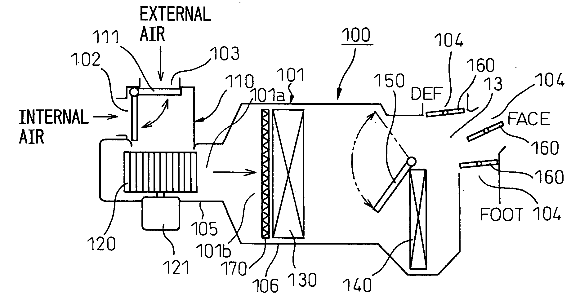
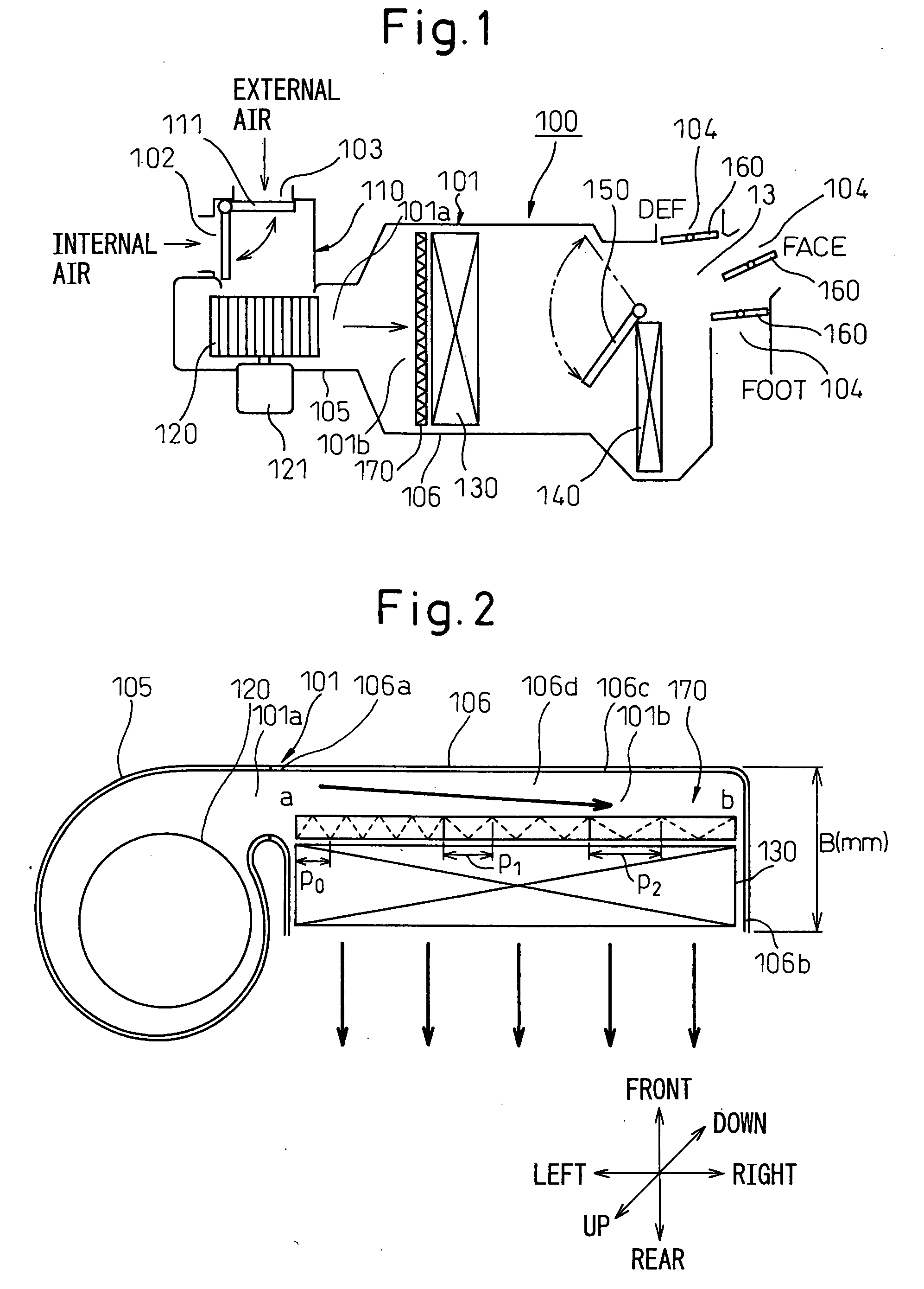
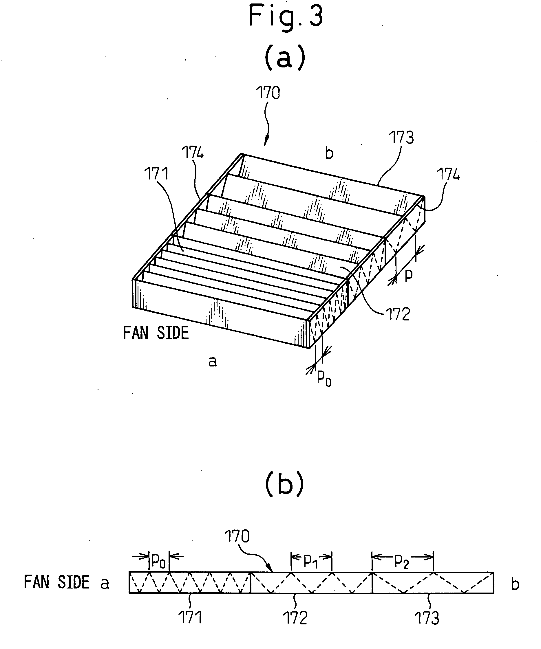
[0051]FIG. 2 shows characterizing portions of a car air conditioner according to the first embodiment of the present invention, that is, a blower offset HVAC (Heating Ventilating and Air Conditioning) unit. FIG. 3 is a perspective view of a filter of the first embodiment and is its explanatory view.

[0052]The car air conditioner according to the present invention can be broadly divided into a blower unit A and an air conditioning unit B. The blower unit A is arranged at a position that is offset from the center of the instrumental panel (not shown in the drawing) on the front side inside the passenger compartment towards the passenger's seat (towards the left in the transverse direction of the car body in the case of right-hand steering wheel cars). In contrast, the air conditioning unit B is arranged in the center of the instrumental panel on the front side of the passenger compartment.

[0053]The blower unit A includes an internal air / external air switching box (see FIG. 1) for selec...

second embodiment

[0065]FIG. 5 shows a filter according to the second embodiment. In the second embodiment, the filter 170 is constituted by three zones 171, 172 and 173 and the fold pitch P of each zone is gradually changed in three stages in the same way as in the first embodiment. However, whereas the fold pitch P of each zone is greater than the optimal pitch Po at a position spaced further apart from the side of the blower fan 120 in the first embodiment, fold is made at the optimal pitch Po providing the lowest airflow resistance Pa in the first zone 171 in the proximity of the blower fan 120 in this second embodiment. In the second and third zones 172, 173 that are spaced apart from the blower fan 120, the fold pitch P is made smaller to a pitch providing greater airflow resistance ΔP that provides large influences of fluid friction. Incidentally, the number of the zones of the filter 170 is not limited to three and the filter needs only be divided into a plurality of zones.

third embodiment

[0066]FIG. 6 shows a filter according to the third embodiment. In the third embodiment, the filter 170 is constituted of three zones 171, 172 and 173. The tuck weaving pitch P of the first zone 171 in the proximity of the blower fan 120 is set to the optimal pitch Po. In the second zone 172 spaced apart progressively from the blower fan 120, the fold pitch P is greater than the optimal pitch Po and in the third zone 173, the fold pitch P is made smaller than the optimal pitch Po. It is possible in this way to set the fold pitch P to the optimal pitch Po in the first zone 171 closest to the blower fan 120 and to have the fold pitch greater or smaller than the optimal pitch Po in the zones 172 and 173 at positions spaced away from the blower fan 120. In this case, similar functions and effects can be obtained as in the first embodiment.


PUM

PropertyMeasurementUnit
Angleaaaaaaaaaa
Massaaaaaaaaaa
Electrical resistanceaaaaaaaaaa

Abstract

A construction of a filter 170 that allows air stream from a blower fan 120 to pass through a heat exchanger 130 arranged adjacent to the blower fan 120 after its flowing direction is changed by about 90 degrees. The filter 170 is disposed on the front surface of the heat exchanger on the upstream side of the air flow and has a construction such that airflow resistance of the filter gradually changes with respect to the flow velocity of air passing through the filter and in this way, flow velocity distribution of air passing through the heat exchanger becomes uniform. In this case, a fold pitch P of folds of the filter that is folded or a peak height h of the folds is changed in a plurality of steps or without any steps.

Description

BACKGROUND OF THE INVENTION[0001]1. Field of the Invention[0002]This invention relates to a car air conditioner equipped with a filter for purifying air inside a passenger compartment.[0003]2. Description of the Related Art[0004]An HVAC (Heating Ventilating and Air Conditioning) unit of a car air conditioner according to the prior art employs a so-called “blower offset installation system” in which a blower fan 1 is arranged adjacent to an evaporator (heat exchanger) 8 in a transverse direction of a car body as shown in FIG. 13. In this case, a folded filter 7 shown in FIG. 13 is arranged on the upstream side of the blower fan 1 in an air flowing direction. A wall surface of a case portion 6 opposing the heat exchanger 8 is shaped into a step shape on the upstream side of the heat exchanger 8 and each step portion is inclined so that a gap between the wall surface of the case portion 6 and the heat exchanger 8 becomes progressively smaller at positions spaced away from the fan 1 in ...

Claims


Application Information

Patent Timeline
IPC IPC(8): B60H1/30B60H3/00
CPCB01D46/521B01D46/522B60H3/0658B01D2279/50B60H3/0608B01D2273/30B01D46/10
Inventor SHIMOYAMA, YOUHEIITOH, KOUJI
Owner DENSO CORP
Why Eureka
Try Eureka