Insertion device for intraocular lens
a technology for insertion devices and ocular lenses, which is applied in the field of insertion devices, can solve the problems of affecting the operation of the operator or the assistant, affecting the operation of the operator, and affecting the operation of the ocular lens, and achieves the effect of preventing liquid leakag
- Summary
- Abstract
- Description
- Claims
- Application Information
AI Technical Summary
Benefits of technology
Problems solved by technology
Method used
Image
Examples
experiment 1
[0119] First, as shown in FIG. 12 (the upperside shows a top view and the lowerside shows a side view), a device 19 for supplying a liquid such as physiologic saline was connected to an insertion device 2′ via a tube 18 and an experiment was conducted. At this time, the insertion device 21 did not have a cover ring 13 or a configuration corresponding thereto. A flow path through which the liquid passes was provided in a pushing shaft 16′, and the tube 18 was connected to the pushing shaft 16′.
[0120]When the liquid was continuously introduced into the eyeball from the liquid supply device 19 via the insertion device 2′ (a nozzle portion 12c), it was confirmed that ocular tension increased and the anterior chamber was filled with the liquid, and the posterior capsule of the crystalline lens moved toward the vitreous body (the anterior chamber was inflated). It was found that when the liquid of a predetermined flow rate can be continuously supplied from the liquid supply device 19 to t...
experiment 2
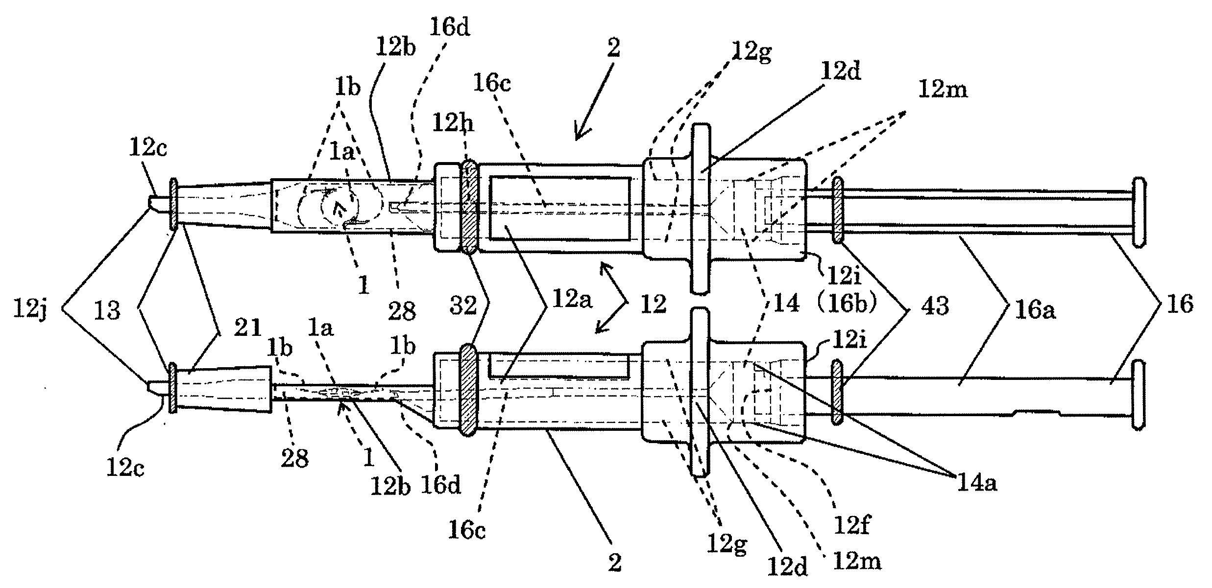
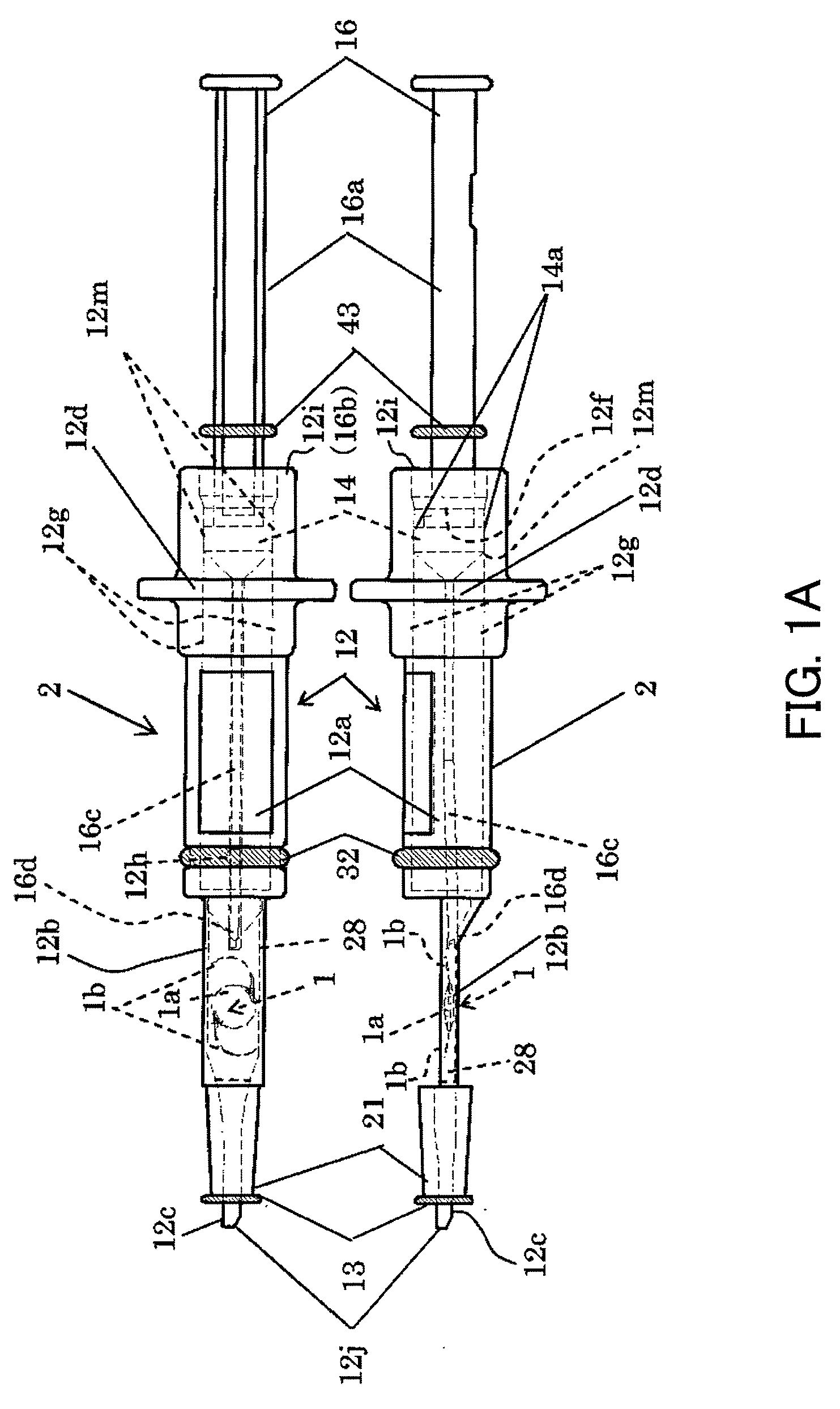
[0121] An experiment was conducted using an insertion device 2 in which a liquid of 25 ml was previously introduced into a main body 12 as shown in FIG. 13. In this experiment, a nozzle portion 12c did not have a cover ring 13 or a configuration corresponding thereto. In this case, even if a pushing shaft 16 was pushed to introduce most of the liquid in the main body 12 into the eye, ocular tension hardly increased from ocular tension when an incision was formed, and the posterior capsule of the crystalline lens did not move toward the vitreous body. The reason that the ocular tension did not increase was studied and found. It was because the incision was linearly formed by a knife, and the three-dimensional nozzle portion 12c was inserted into the incision to form a gap 20 in FIG. 11, and a liquid L leaked from the gap 20 as shown in FIG. 14.
experiment 3
[0122] A cover ring 13 was mounted to the nozzle portion 12c of the insertion device 2 used in Experiment 2, and the cover ring 13 was brought into tight contact with a portion near the incision 15a in the eyeball 15 as shown in FIG. 15, and an experiment similar to Experiment 2 was conducted. In this case, ocular tension increased and the posterior capsule of the crystalline lens moved toward the vitreous body. It was confirmed that this was because a gap 20 is created outside the nozzle portion 12c in the incision 15a, but the cover ring 13 is brought into tight contact with around the incision 15a in the eyeball 15, and thus even if the liquid flows out of the gap 20, a seal by the cover ring 13 prevents the liquid from leaking outside. In particular, the cover ring 13 has a circular section, and thus the cover ring 13 is brought into ring-shaped line contact around the incision 15a in the eyeball 15. Thus, it can be considered that a sealing effect was able to be obtained more e...
PUM
 Abstract
Description
Claims
Application Information
 - R&D
- Intellectual Property
- Life Sciences
- Materials
- Tech Scout
- Unparalleled Data Quality
- Higher Quality Content
- 60% Fewer Hallucinations
Browse by: Latest US Patents, China's latest patents, Technical Efficacy Thesaurus, Application Domain, Technology Topic, Popular Technical Reports.
© 2025 PatSnap. All rights reserved.Legal|Privacy policy|Modern Slavery Act Transparency Statement|Sitemap|About US| Contact US: help@patsnap.com


