Patient Video and Audio Monitoring System

a monitoring system and audio technology, applied in the field of patient monitoring, can solve the problems of not being able to enable seamless web-based seamless switching from patient to patient, known systems are unable to utilize a virtual interface for selecting and controlling the camera of the monitoring system, and known systems are unable to address the problem of processing patient (and other context) information

Inactive Publication Date: 2007-11-22
SIEMENS MEDICAL SOLUTIONS USA INC
View PDF17 Cites 70 Cited by
  • Summary
  • Abstract
  • Description
  • Claims
  • Application Information

AI Technical Summary

Benefits of technology

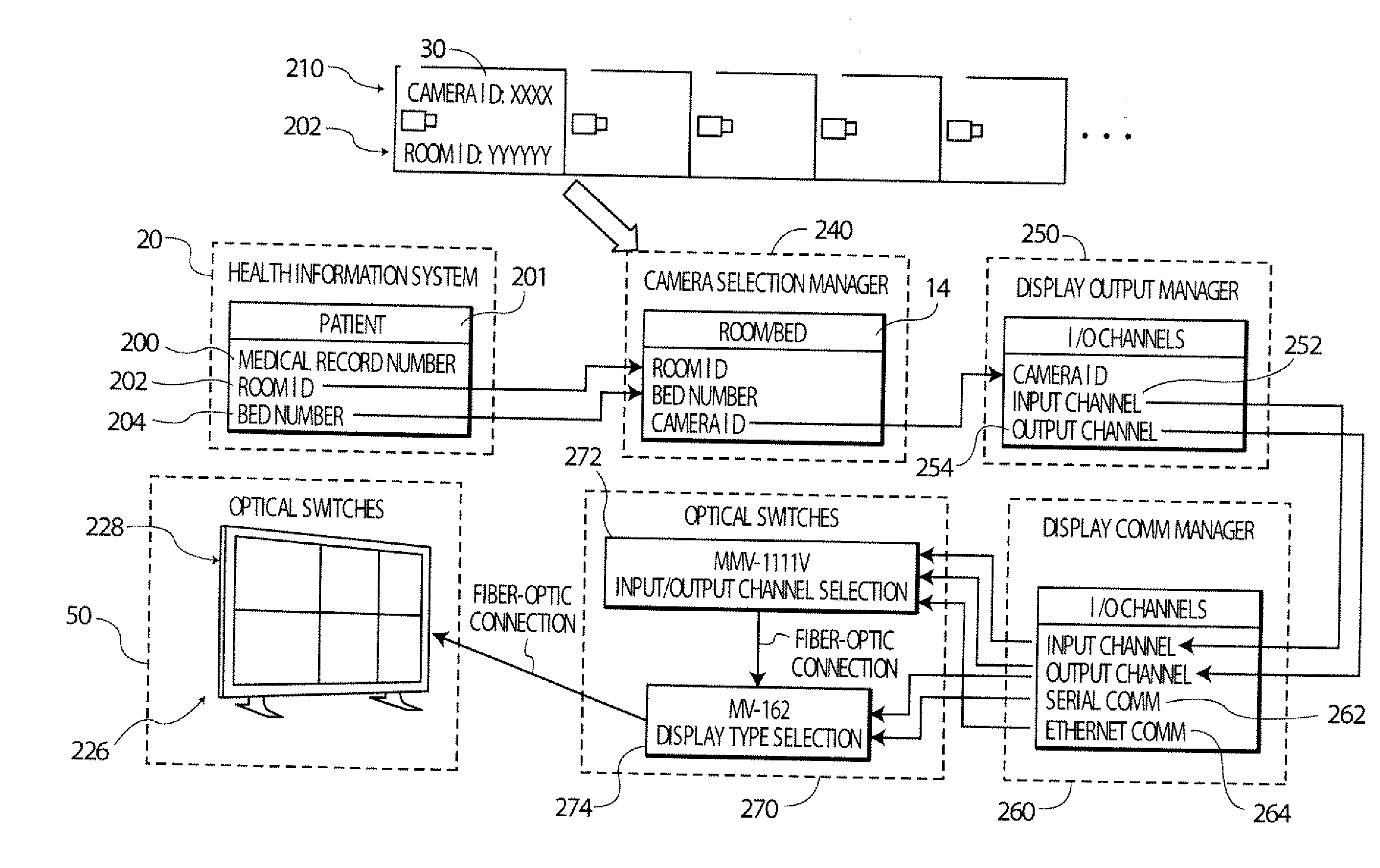
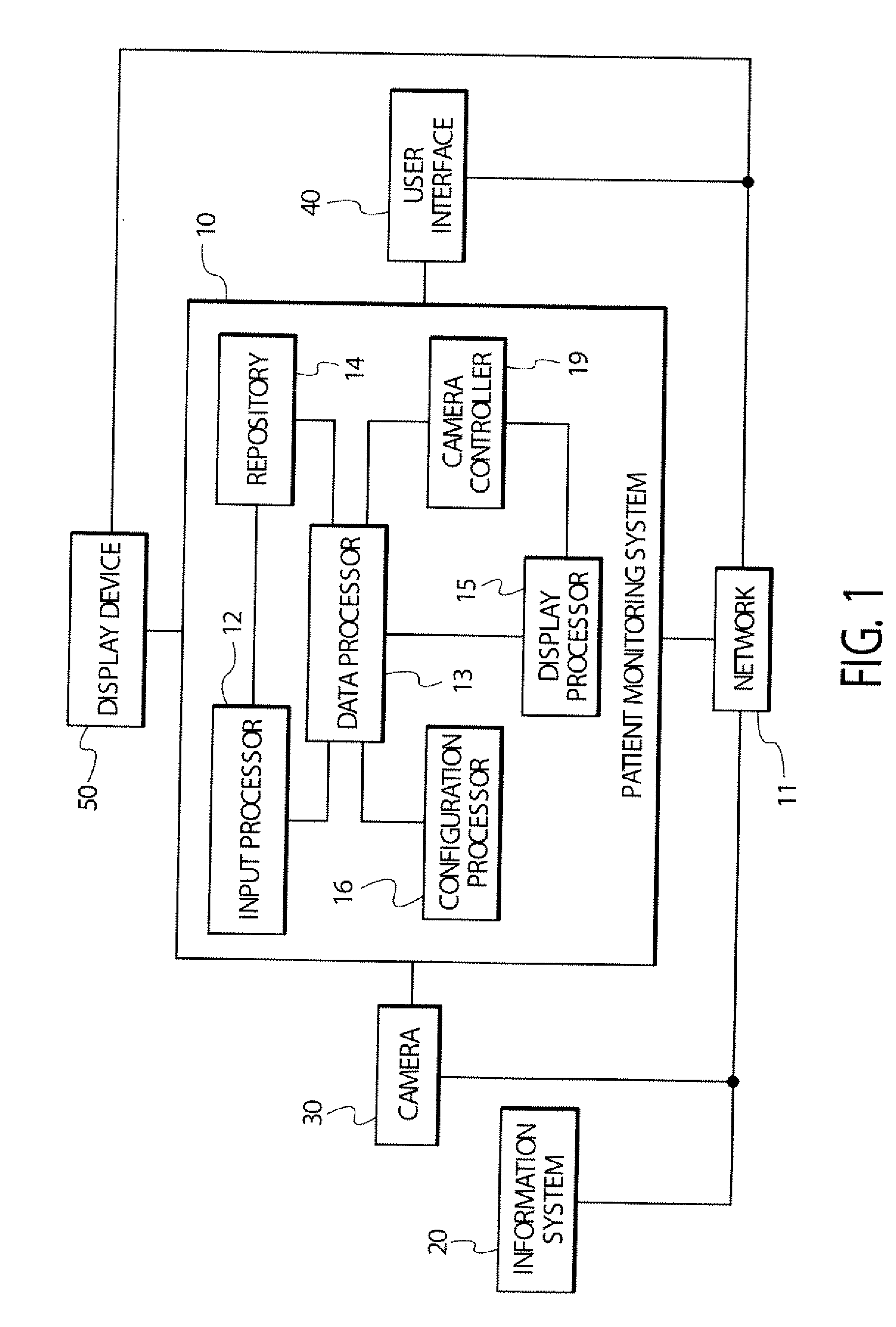
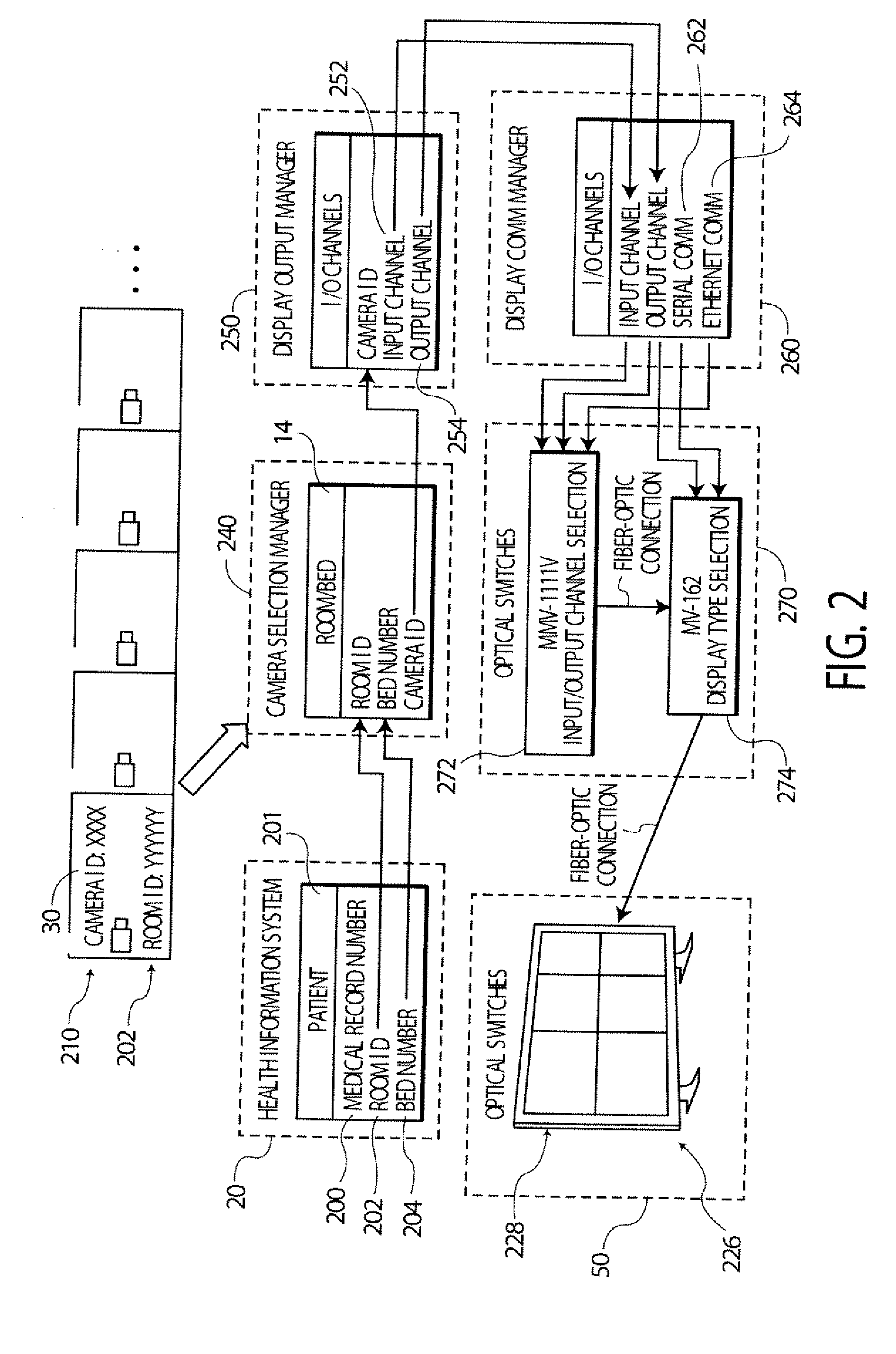
[0005] A remote patient monitoring system according to invention principles enables visual monitoring of a plurality of patients in different locations concurrently from multiple (e.g., mobile) monitoring systems at a plurality different remote locations. An input processor receives a patient identifier derived from user interaction with an executable application. At least one repository of mapping information associates patient identifiers with corresponding camera identifiers and room identifiers enabling acquisition of video information from a location associated with a particular patient. A data processor uses the mapping in

Problems solved by technology

Known systems fail to address the problem of processing patient (and other context) information using a Web-based application involved in processing a camera image of at least one patient or multiple patients concurrently and related patient data using an optical switch and IP networking architecture.
Known systems fail to enable web-based cohesive automatic switching from patient to patient as alerts and warnings occur.
Known systems are unable to utilize a virtual interface for selection and control of cameras of the monitoring system.
Virtual user interfaces (gaming, for instance) a

Method used


Image

  • Patient Video and Audio Monitoring System
  • Patient Video and Audio Monitoring System
  • Patient Video and Audio Monitoring System

Examples


Embodiment Construction

[0024] A processor, as used herein, operates under the control of an executable application to (a) receive information from an input information device, (h) process the information by manipulating, analyzing, modifying, converting and / or transmitting the information, and / or (c) route the information to an output information device. A processor may use, or comprise the capabilities of, a controller or microprocessor, for example. The use of the term manager or controller, as used herein may be synonymous with the term processor. The processor may operate with a display processor or generator. A display processor or generator is a known element for generating signals representing display images or portions thereof. A processor, manager and a display processor comprises any combination of hardware, firmware, and / or software.

[0025] An executable application, as used herein, comprises code or machine readable instructions for conditioning the processor to implement predetermined functio...


PUM


Abstract

A user interface and software system and architecture enables linking medical record information and patient location to a camera associated with that location when a particular patient is selected by a clinician using a health information system. The image of the patient as recorded by an in-room camera is displayed within a picture-in-picture display on a large plasma screen located at a command station, for example. The image may be controlled by a remote camera controller employing a Web-based user interface that allows a user to implement a pan-tilt-zoom (PTZ) camera controller via mouse control, for example. Information relating to patient location is used to remotely control, via Web-based application, the selection of the appropriate camera and the type of display in which to show the image. The user interface associated with this architecture provides an efficient and intuitive means of selecting specific images and specific display styles. The system operates in a parent-child relationship in which information associated with a parent application (HIS, for instance) is passed to the application architecture, thereby providing a direct, error-free and positive link to the application.

Description

[0001] The present patent application derives priority from U.S. Provisional Patent Application Serial Number 60 / 796,775 by J. Zaleski filed May 2, 2006 and U.S. Provisional Patent Application Ser. No. 60 / 747,095 by J. Zaleski filed May 12, 2006.FIELD OF THE INVENTION [0002] The present invention relates generally to the field of patient monitoring, and more specifically to a system for selecting and viewing audio-video data in combination with other data over a network. BACKGROUND OF THE INVENTION [0003] In many industries a plurality of systems exist that enable users to monitor the actions of at least one other person by controlling the operation of a camera able to capture audio and video data representative of at least one person. Systems such as these are advantageous in the security and gaming industries as there is a need to continually monitor people and locations concurrently with other data. However, audio-visual monitoring systems are also advantageous in the healthcare ...

Claims


Application Information

Patent Timeline
IPC IPC(8): G06F19/00A61B5/00
CPCA61B5/1113A61B5/0013G06Q50/24G16H40/67
Inventor ZALESKI, JOHN R.
Owner SIEMENS MEDICAL SOLUTIONS USA INC
Why Eureka
Try Eureka