Storage control apparatus, data management system and data management method

Inactive Publication Date: 2007-11-22
HITACHI LTD
View PDF9 Cites 59 Cited by
  • Summary
  • Abstract
  • Description
  • Claims
  • Application Information

AI Technical Summary

Benefits of technology

[0018] According to an aspect of an apparatus of the present invention, there is provided a storage control apparatus includes a plurality of connecting units connected to at least one host computer and at least one hard disk drive as storage medium for storing data; at least one non-volatile storage medium that is of a

Problems solved by technology

Generally, in a storage system having a larger capacity that uses hard disk drives (hereinafter referred to as HDD), power consumption increases in proportion to increase in capacity of storage media.
However, a flash memory has a limitation on cycles of writing due to a physical property of cells for retaining information.
Although the above scheme has enhanced efficiencies in limitation on cycles of writing for a flash memory device, with respect to distribution of storage area at an element level, there has been remaining limitation on cycles of writing for the flash memory device.
The flash memory has a further disadvantage in that writing sp

Method used


Image

  • Storage control apparatus, data management system and data management method
  • Storage control apparatus, data management system and data management method
  • Storage control apparatus, data management system and data management method

Examples


first embodiment

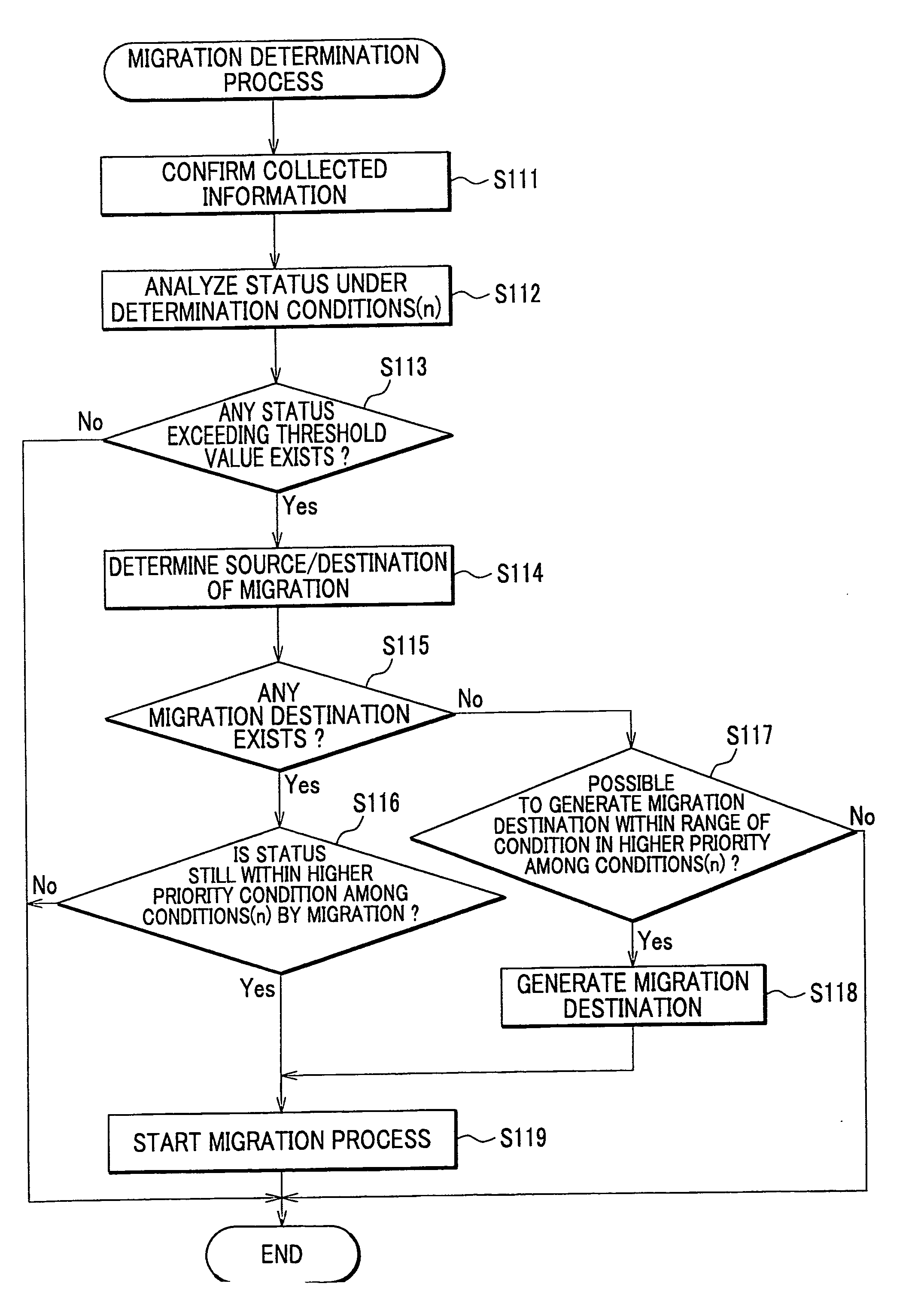
[0045] With reference to the attached drawings, a detailed description will be given on a storage system S according to the first embodiment of the present invention as follows.

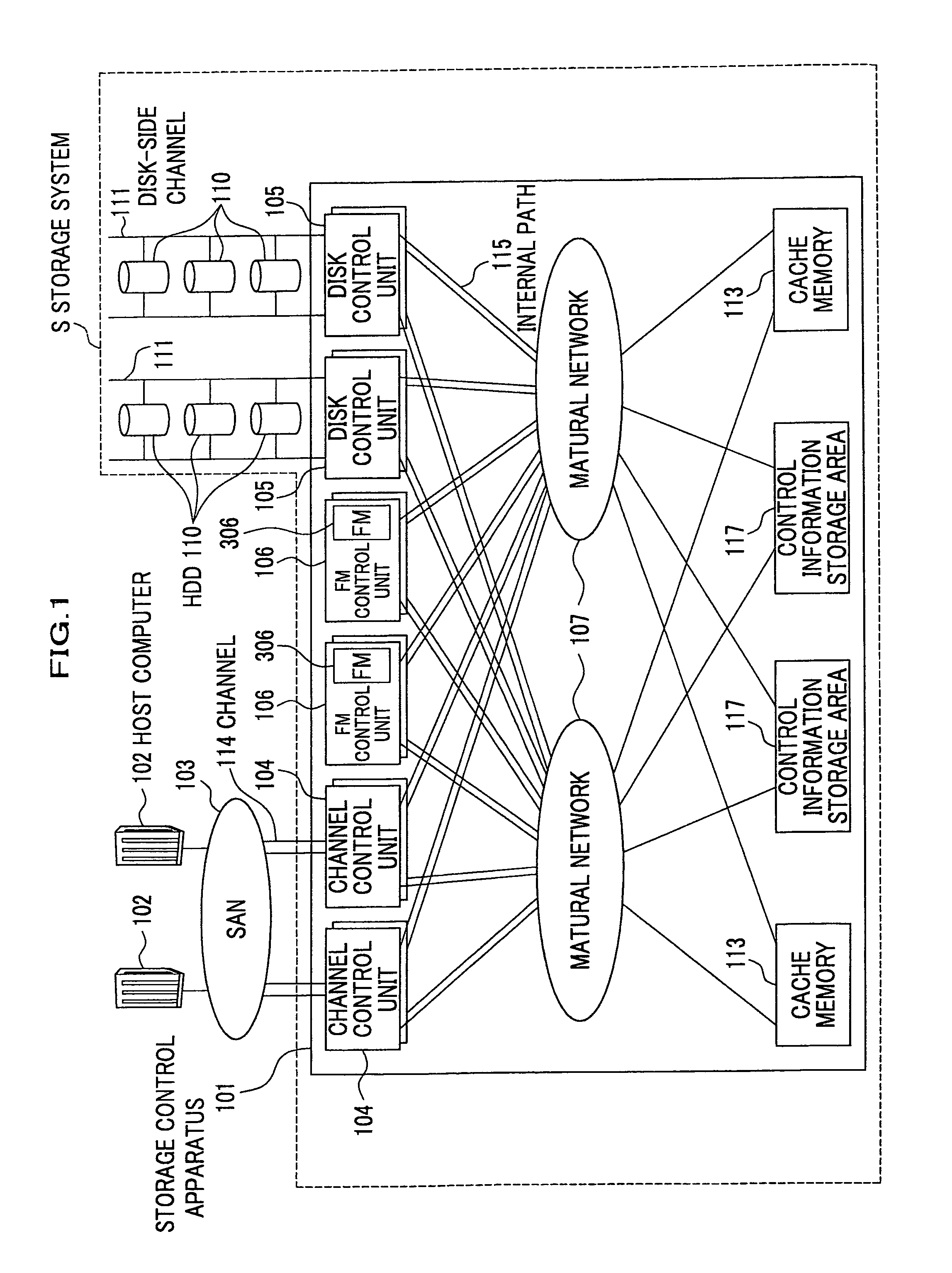
[0046]FIG. 1 is a block diagram showing an outline of a configuration of an embodiment of the present invention including a storage system. The storage system S comprises a storage control apparatus 101 and HDDs (hard disk drives) 110. The storage control apparatus 101 is connected through channels 114 via SAN (storage Area Network) 103 comprising SAN switches to one or plural host computers 102 (two in the drawing).

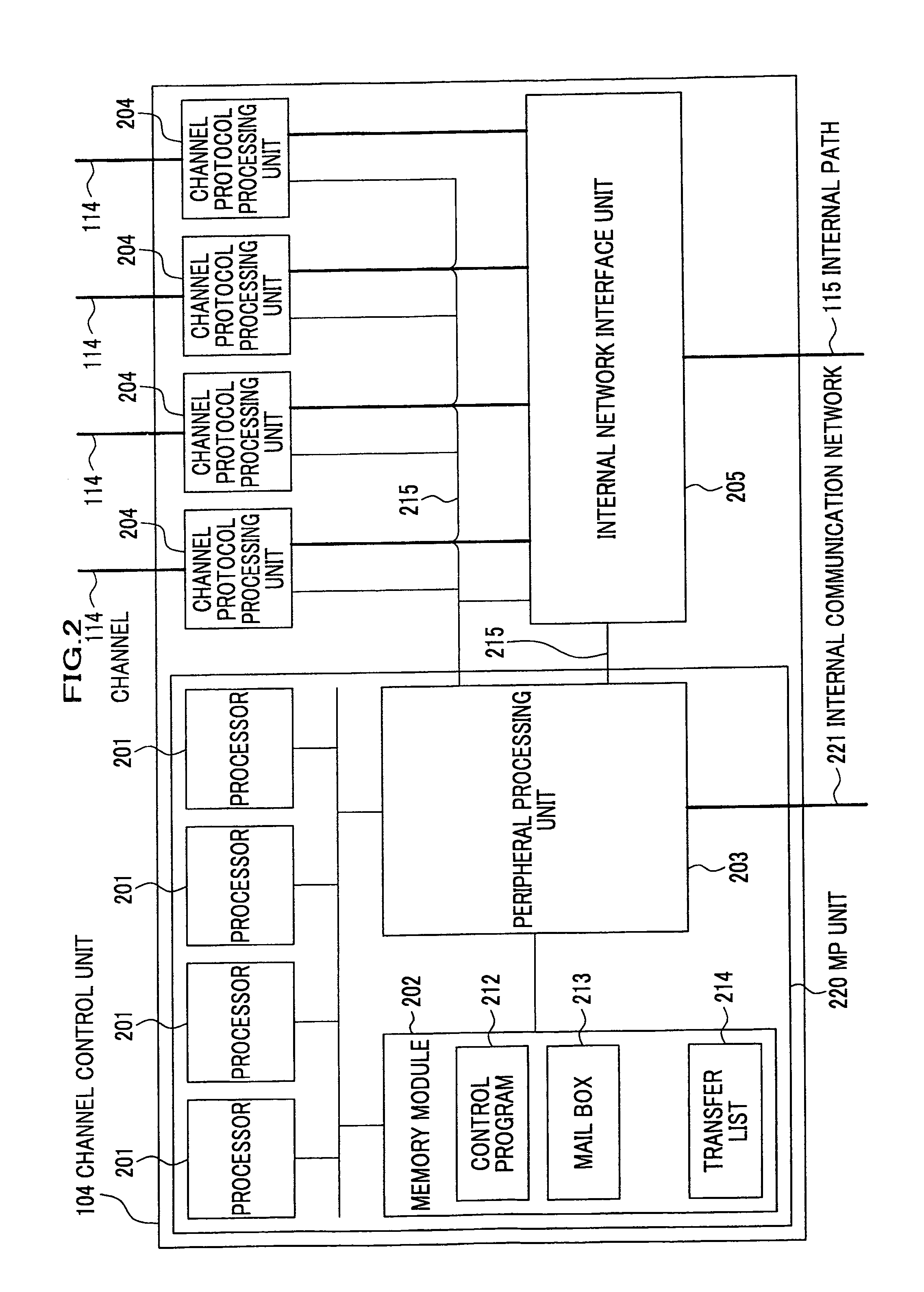
[0047] The storage control apparatus 101 is also connected to a plurality of HDDs 10 for storing data through disk-side channels 111. The storage control apparatus 101 comprises a plurality of channel control units (connecting units) 104, a plurality of cache memories (memory units) 113, control information storage areas (memory units) 117, a plurality of disk control units (connecting units) 10...

second embodiment

[0174] Hereinafter, detailed descriptions will be given on a storage system S according to a second embodiment of the present invention, with reference to the attached drawings.

[0175] Note that, in the descriptions on the second embodiment, the same components as those in the first embodiment are denoted by the same numeral references of the first embodiment, and components of the storage system S that are not described in the second embodiment are substantially the same as those of the first embodiment of the present invention.

[0176] In the second embodiment, explanations will be given particularly on how to allocate data storing locations, which is one of functions performed in the management terminal 601 or the management unit 603. To be specific, the explanations will be given on how to perform processes of selecting data storing locations when a user specifies data attributes or data usage requirements.

[0177] Management programs, executed on the storage control device 101 or...


PUM


Abstract

A storage control apparatus according to the present invention includes a plurality of connecting units connected to one or more host computers and one or more hard disk drives as storage media for storing data, one or more non-volatile storage media which are of a different type from the hard disk drives and which store data WRITE requested from the host computer, a plurality of processing units for processing WRITE and READ requests from the host computer by using the hard disk drives or the non-volatile storage media and, a plurality of memory units for storing control information to be by the processing units.

Description

CROSS-REFERENCE TO RELATED APPLICATIONS [0001] This is a continuation-in-part application of U.S. application Ser. No. 11 / 258,282 filed Oct. 26, 2005, the subject matter of which is incorporated by reference herein. This application claims the benefit of Japanese Patent Applications 2005-275018 filed on Sep. 22, 2005 and 2006-227277 fined on Aug. 24, 2006, the disclosures of which are incorporated herein by reference.BACKGROUND OF THE INVENTION [0002] 1. Field of the Invention [0003] The present invention relates to a technology for reducing power consumption in a storage control apparatus for storing data in at least one hard disk device and other storage media. The present invention also relates to storage systems including a storage apparatus, in particular, a storage control apparatus or a tape library control apparatus for storing data on one or more disk devices or storage media; solid state disk devices such as optical disk library control apparatuses and silicon disk control...

Claims


Application Information

Patent Timeline
IPC IPC(8): G06F12/00
CPCG06F3/0613G06F3/0616G06F3/0625Y02B60/1246G06F3/0649G06F3/067G06F3/0685G06F3/0631Y02D10/00
Inventor FUJIBAYASHI, AKIRAFUJIMOTO, KAZUHISANAKAMURA, SHUJI
Owner HITACHI LTD
Why Eureka
Try Eureka